Plasma display system

A display device and plasma technology, applied in identification devices, TVs, color TVs, etc., can solve the problems of reducing strength and achieve the effect of improving deformation strength

Inactive Publication Date: 2009-03-04
HITACHI LTD
View PDF1 Cites 4 Cited by
  • Summary
  • Abstract
  • Description
  • Claims
  • Application Information

AI Technical Summary

Problems solved by technology

However, since the rigidity will decrease if the bottom plate is thinned, the strength against deformation may be reduced when vibrations during transportation, etc.
In the plasma display device described in the above-mentioned Patent Document 1, although the deformation strength can be improved by providing the frame behind the bottom plate, there is still room for further improvement in the deformation strength.

Method used


Image

  • Plasma display system
  • Plasma display system
  • Plasma display system

Examples


Embodiment Construction

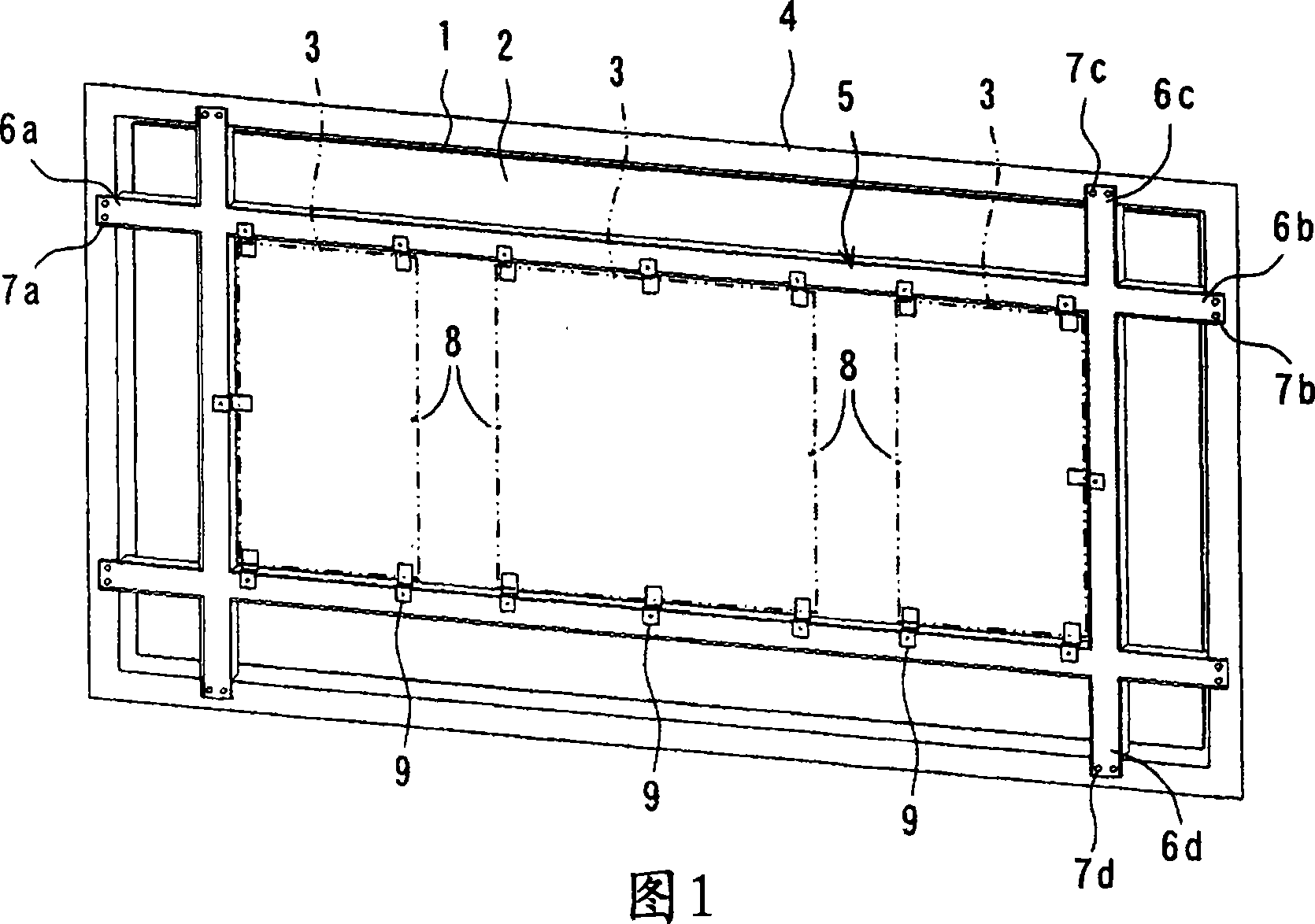
[0014] One embodiment of the present invention will be described below with reference to the drawings. FIG. 1 is a perspective view showing the structure of an embodiment of the plasma display device of the present invention.

[0015] In FIG. 1, the plasma display device includes: a plasma display panel (Plasma Display Panel: hereinafter referred to as "PDP") 1; a plate-like base plate 2 bonded to the back of the PDP1 with an adhesive material or the like; a circuit for outputting electrical signals to the PDP1 Substrate 3; Housing 4 for accommodating PDP1, backplane 2, and circuit substrate 3.

[0016] On the rear surface of the bottom plate 2, reinforcing members 5 having, for example, a U-shaped cross section are arranged in a grid pattern. In the present embodiment, two reinforcing members 5 are arranged to extend in the longitudinal direction (upper left and lower right directions in FIG. 1 ) and the width direction (upper and lower directions in FIG. 1 ) of the bottom p...


PUM


Abstract

A plasma display system capable of enhancing stiffness against deformation. The system comprising a plasma display panel (PDP) 1; a sheet-like chassis 2 bonded to a back surface of the PDP 1; a circuit board 3 outputting an electric signal to the PDP 1; a casing 4 accommodating therein the PDP 1, the chassis 2, and the circuit board 3; a reinforcement member 5 disposed as an adjunct at a back surface of the chassis 2, the reinforcement member 5 extending in a plane direction of the chassis 2 to stick outwardly therefrom; and a fixing means (e.g. through holes 7a to 7d) disposed in each of overhangs 6a to 6d of the reinforcement member 5 sticking out in a plurality of directions from the chassis 2, the fixing means fixing the casing 4 in place.

Description

technical field [0001] The present invention relates to a plasma display device that displays images using a plasma display panel. Background technique [0002] A plasma display device generally includes: a plasma display panel (Plasma Display Panel: hereinafter referred to as "PDP"); a plate-like base plate joined behind the PDP; a circuit substrate that outputs electrical signals to the PDP; accommodating these PDPs, base plates, and circuit substrates Housing (for example, refer to Japanese Patent Document 1). [0003] In the plasma display device described in Patent Document 1, a ladder-shaped frame is attached to the rear surface of the chassis. In addition, the inner part behind the bottom plate is provided with: a first boss formed with a threaded hole for installing the circuit board; a second boss formed with a threaded hole for installing the back cover. In addition, the circuit board is screw-fixed on the first boss. The back cover is supported by brackets inst...

Claims


Application Information

Patent Timeline
Patent Type & Authority Applications(China)
IPC IPC(8): G09F9/313G09F9/00H04N5/64
CPCH05K5/02H01J11/34
Inventor 福山满由美田之口亮斗
Owner HITACHI LTD
Why Eureka
Try Eureka