Dynamic performance detection method for foam materials or soft materials
A foam material and dynamic performance technology, which is applied to the measurement, measurement device, and analysis material of the property force of piezoelectric resistance materials, can solve the problems of complex test methods and low measurement sensitivity, and achieve simple and easy measurement. The effect of high sensitivity and wide frequency response
- Summary
- Abstract
- Description
- Claims
- Application Information
AI Technical Summary
Problems solved by technology
Method used
Image
Examples
Embodiment 1
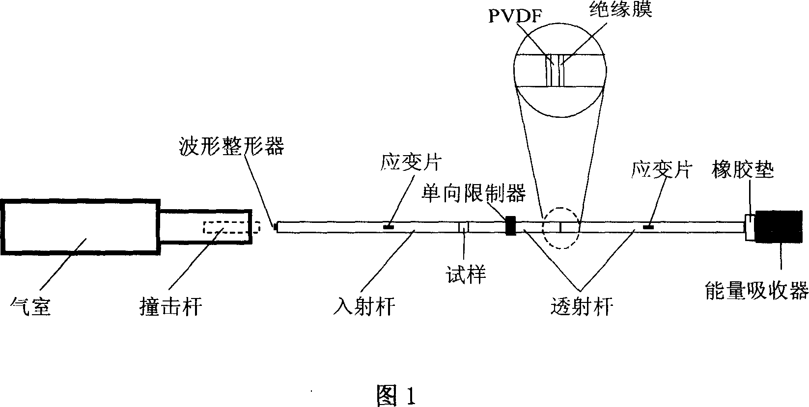
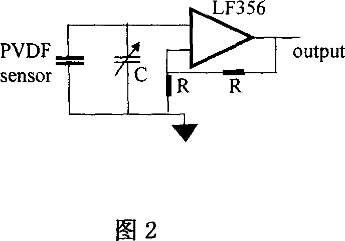
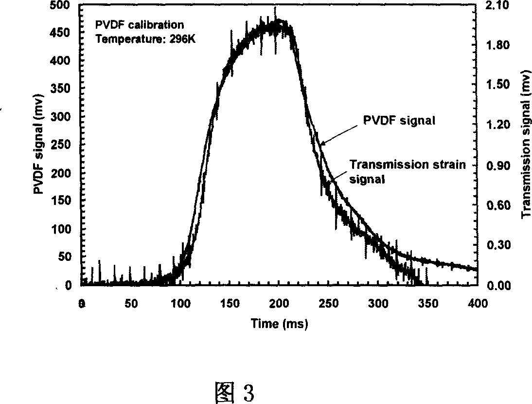
[0015] Embodiment 1: With reference to Figures 1 to 3, the present invention first divides the transmission rod of the Hopkinson pressure rod into two sections, then takes a piezoelectric film with a thickness of 10 μm, and pastes a micron-scale insulating film on both sides thereof, and then The piezoelectric film with the insulating film pasted is clamped between two transmission rods, and a one-way limiter is installed in the middle of a transmission rod close to the sample. The one-way limiter is fastened to the transmission rod with a clamp sleeve, and only It is allowed to move away from the sample; the other section of the transmission rod is close to the fixed energy absorber through the rubber pad, and the pre-tightening force of the piezoelectric film is adjusted through the rubber pad. The output electrode of the piezoelectric film is electrically connected to the impedance transformer, and the impedance transformer adopts LF356 field effect device, and the impedance...
Embodiment 2
[0016] Embodiment 2: With reference to Figures 1 to 3, the present invention first divides the transmission rod of the Hopkinson pressure rod into two sections, then takes a piezoelectric film with a thickness of 30 μm, and pastes a micron-level insulating film on both sides thereof, and then The piezoelectric film with the insulating film pasted is clamped between two transmission rods, and a one-way limiter is installed in the middle of a transmission rod close to the sample. The one-way limiter is fastened to the transmission rod with a clamp sleeve, and only It is allowed to move away from the sample; the other section of the transmission rod is close to the fixed energy absorber through the rubber pad, and the pre-tightening force of the piezoelectric film is adjusted through the rubber pad. The output electrode of the piezoelectric film is electrically connected to the impedance transformer, and the impedance transformer adopts LF356 field effect device, and the impedance...
Embodiment 3
[0017] Embodiment 3: With reference to Figures 1 to 3, the present invention first divides the transmission rod of the Hopkinson pressure rod into two sections, then takes a piezoelectric film with a thickness of 50 μm, and pastes a micron-scale insulating film on both sides thereof, and then The piezoelectric film with the insulating film pasted is clamped between two transmission rods, and a one-way limiter is installed in the middle of a transmission rod close to the sample. The one-way limiter is fastened to the transmission rod with a clamp sleeve, and only It is allowed to move away from the sample; the other section of the transmission rod is close to the fixed energy absorber through the rubber pad, and the pre-tightening force of the piezoelectric film is adjusted through the rubber pad. The output electrode of the piezoelectric film is electrically connected to the impedance transformer, and the impedance transformer adopts LF356 field effect device, and the impedance...
PUM
| Property | Measurement | Unit |
|---|---|---|
| thickness | aaaaa | aaaaa |
Abstract
Description
Claims
Application Information
 - R&D
- Intellectual Property
- Life Sciences
- Materials
- Tech Scout
- Unparalleled Data Quality
- Higher Quality Content
- 60% Fewer Hallucinations
Browse by: Latest US Patents, China's latest patents, Technical Efficacy Thesaurus, Application Domain, Technology Topic, Popular Technical Reports.
© 2025 PatSnap. All rights reserved.Legal|Privacy policy|Modern Slavery Act Transparency Statement|Sitemap|About US| Contact US: help@patsnap.com


