Supercharge Your Innovation With Domain-Expert AI Agents!

Picture splitting device

A technology of screen segmentation and screen, applied in the direction of cathode ray tube indicators, instruments, closed-circuit television systems, etc., can solve the problems of small selectivity, occupying CPU resources, etc., and achieve the effect of low cost

Inactive Publication Date: 2010-06-02
ZHEJIANG HUATU MICROCHIP TECH CO LTD
View PDF5 Cites 0 Cited by
  • Summary
  • Abstract
  • Description
  • Claims
  • Application Information

AI Technical Summary

Problems solved by technology

[0002] At present, one of the known picture splitter implementations is that the splicing method is simple, and can only realize single-picture, four-picture, and nine-picture picture splicing formats, and the user has very little choice, and can only switch between several picture splicing modes; One is to use software to realize complex picture splicing formats, which can realize various picture divisions and various patrol operations of channels, but it takes up a lot of CPU resources

Method used


Image

  • Picture splitting device
  • Picture splitting device
  • Picture splitting device

Examples


Embodiment Construction

[0034] The present invention will be further described below in conjunction with the accompanying drawings.

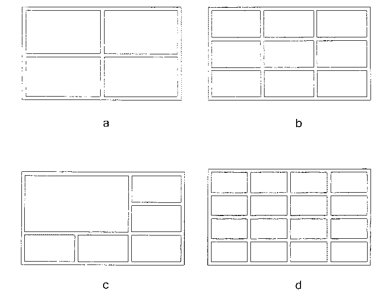
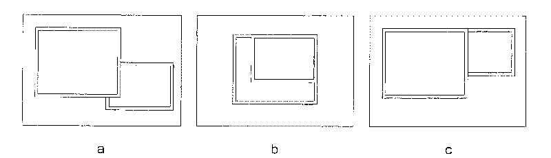
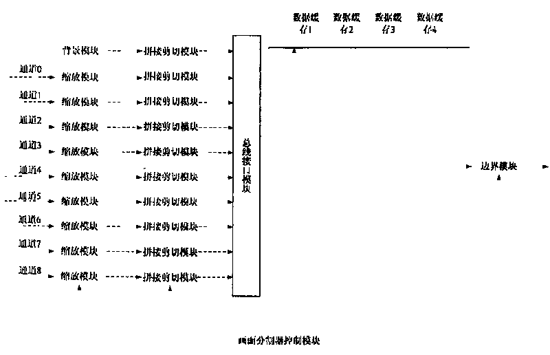
[0035] refer to Figure 1 to Figure 7 , a screen splitting device, comprising: a screen scaling module, configured to perform a scaling operation on a screen of an input data source to obtain a standard rectangular data source; a screen cutting module, configured to convert the data of each channel according to a user-defined The priority relationship, the corresponding coordinate position, and the form in which the final target image exists; the screen synchronization buffer module is used to synchronize the data of each channel from their respective clock domains to the clock domain of the final target image, and The clipped data of each channel is saved to the corresponding position of the data buffer according to the relevant coordinates; the boundary module is added, which is used to save the data of each channel to the data buffer according to the priority relati...


PUM


Abstract

The invention relates to a picture partitioning device which comprises a picture zooming module, a picture shearing module, a picture synchronous buffer module, an adding border module and a picture output module, wherein the picture zooming module is used for carrying out the zooming operation of any size of input data flow to obtain standard rectangular data flow; the picture shearing module isused for carrying out the shearing operation of data of each channel according to the user-defined priority relation and the corresponding coordinate positions and the existing form of the final target images; the picture synchronous buffer module is used for synchronizing the data of each channel from respective clock domains thereof to the clock domains of the final target images and storing thesheared data of each channel to the corresponding positions of a data buffer according to the relative coordinates; the adding border module is used for adding borders of the images of each channel on the corresponding positions of the final target images according to the user-defined priority relation, and the border of the channel data with high priority covers the border of the channel with low priority. The invention can realize the picture stitching of any format, and does not basically occupy the CPU source.

Description

technical field [0001] The invention relates to the field of video monitoring, in particular to a screen segmentation device in a multi-channel video data splicing format. Background technique [0002] At present, one of the known picture splitter implementations is that the splicing method is simple, and only can realize single-picture, four-picture, and nine-picture picture splicing formats, and the user has little choice, and can only switch between several picture splicing modes; One is to implement complex image splicing formats through software, which can realize various image divisions and various patrol operations of channels, but it takes up a lot of CPU resources. Contents of the invention [0003] In order to overcome the deficiency that the existing picture splitter needs to occupy a large amount of CPU resources to achieve arbitrary splicing of multi-channel video data, the present invention provides a picture splitting device that can realize splicing of pict...

Claims


Application Information

Patent Timeline
Patent Type & Authority Patents(China)
IPC IPC(8): H04N7/18G09G5/14
Inventor 李中峰秦兴陈琦马云艳姚卫忠
Owner ZHEJIANG HUATU MICROCHIP TECH CO LTD
Features
  • R&D
  • Intellectual Property
  • Life Sciences
  • Materials
  • Tech Scout
  • Unparalleled Data Quality
  • Higher Quality Content
  • 60% Fewer Hallucinations
Learn More