Double flush clinch stud

一种平面板、顶面的技术,应用在制造工具、机械设备、铆钉等方向,能够解决失效、旋转固定削弱等问题,达到高推出力、高齐平安装的效果

Active Publication Date: 2009-03-18
PEM MANAGEMENT INC
View PDF1 Cites 4 Cited by
  • Summary
  • Abstract
  • Description
  • Claims
  • Application Information

AI Technical Summary

Problems solved by technology

Finally, while it is possible to modify the Dupree fastener to allow rotation by removing the knurling in one of the undercuts, the rotation fixation may be significantly weakened and fail after many cycles

Method used


Image

  • Double flush clinch stud
  • Double flush clinch stud
  • Double flush clinch stud

Examples


Embodiment Construction

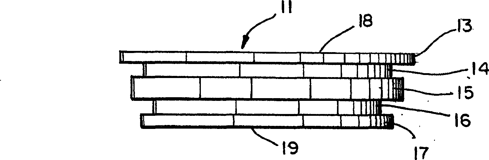
[0017] now refer to figure 1 , the present invention is a fixed type fastener having two pairs of displacers 13 and 15 and associated mutually coaxial adjacent undercuts 14 and 16, the diameter of the first pair 13 and 14 being larger than the other pair . The fastener terminates at the bottom via an end cap 17 . These formations are placed along the shank of the fastener between the top surface 18 and the bottom surface 19 of the end cap 17 .

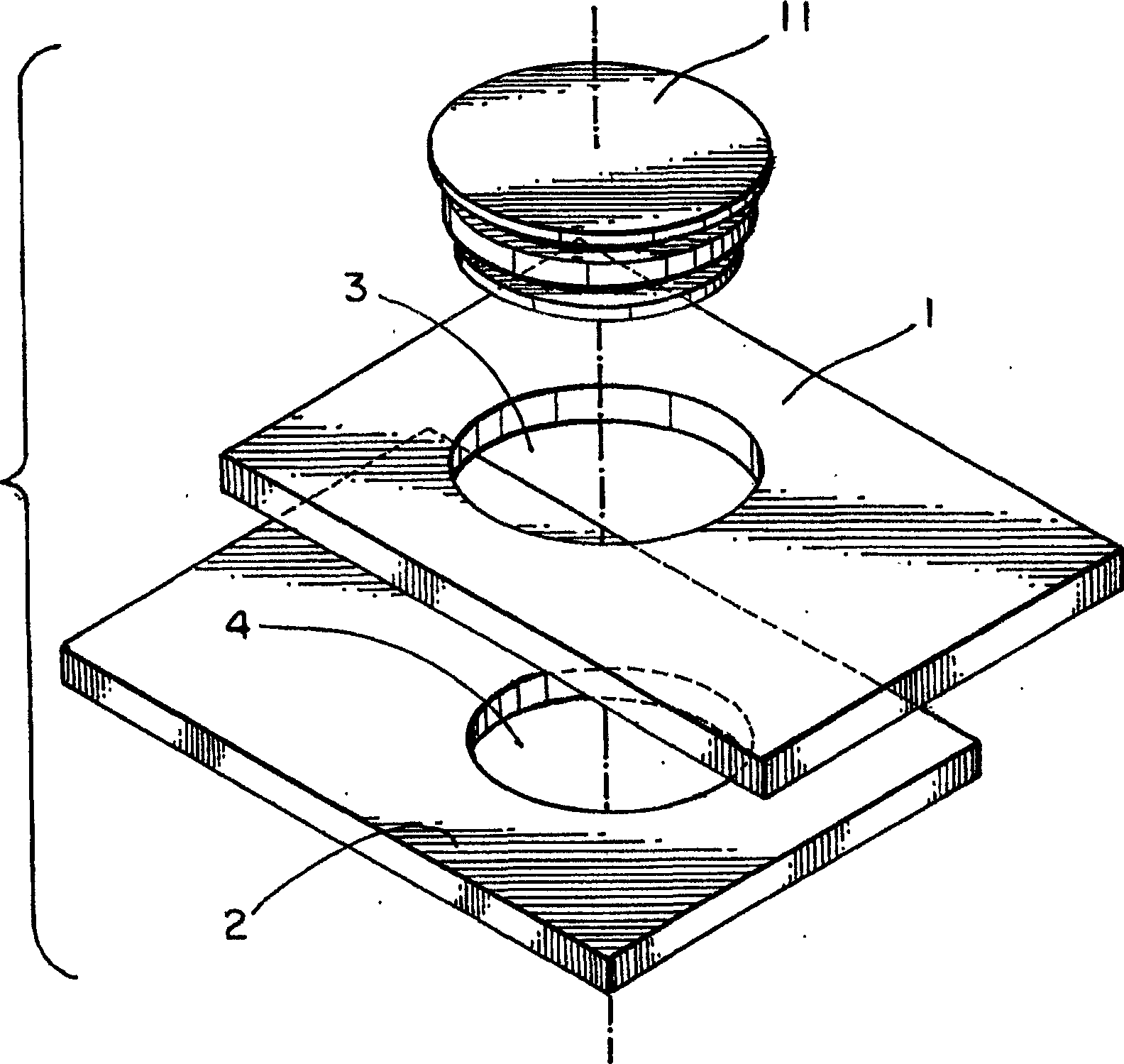
[0018] like figure 2 As shown in , the two boards 1, 2 are held in alignment by the fixed connector of the invention, which is forcibly applied from above. Panels 1 and 2 are shown separately in this figure for illustrative purposes only. The top and second plates comprise aligned holes 3 and 4 having different diameters corresponding to the diameters of the respective displacers and undercuts of the connectors. The diameter of the hole 3 in the top plate is larger than the diameter of the hole 4 in the second plate, allowing the...


PUM


Abstract

A double flush clinch stud includes adjacent clinch means of different diameters with planar end surfaces. The stud may be employed in forming an assembly wherein two metal sheets are joined in face-to-face contacting relationship. This assembly can provide a flush attachment on the outside surfaces of both sheets when the length of the stud is equal to the combined widths of the sheets. In an alternative embodiment, the top undercut groove can be adapted to be underfilled with the material of the top sheet. In this alternate configuration, the top sheet is effectively constrained between the head of the fastener and the second sheet while permitting the top sheet to pivot with respect to the second sheet.

Description

[0001] related application [0002] This application is related to Provisional Patent Application 60 / 620,345, filed October 21, 2004, and entitled "Double Plane Set Bolt," from which priority is claimed. technical field [0003] The present invention relates to a fastener for face-to-face fixing of two metal plates. The invention also relates to fasteners that provide a flush connection to the panels via deformation of the panels. Background technique [0004] Most commonly, metal sheets are fastened together using rivets or spot welds. However, these fastening methods have their disadvantages since spot welding leaves weld scale and burns the surface of the board. Spot welding is also ineffective for sheets that are not easily weldable, eg in the case of very thin or dissimilar materials. Also, burnt boards may leave an unacceptable aesthetic appearance. Rivets can perform a similar function, but they cannot leave a trim level with the surface of the board, which may be...

Claims


Application Information

Patent Timeline
Patent Type & Authority Applications(China)
IPC IPC(8): F16B19/04B23P11/00B21D39/00
CPCF16B5/04B23P19/062Y10T29/4992Y10T403/75F16B19/06
Inventor 麦克J·马隆尼
Owner PEM MANAGEMENT INC
Why Eureka
Try Eureka