Flow sensor unit

A technology of flow sensor and sensor chip, applied in the direction of measuring flow/mass flow, liquid/fluid solid measurement, instruments, etc., can solve the problems of flow sensor 1 output characteristic deterioration, detection accuracy deterioration, etc., to avoid detection accuracy deterioration, output Not easy effect

Inactive Publication Date: 2011-03-30
YAMATAKE HONEYWELL CO LTD
View PDF2 Cites 0 Cited by
  • Summary
  • Abstract
  • Description
  • Claims
  • Application Information

AI Technical Summary

Problems solved by technology

[0006] However, in this flow sensor unit 10, since the sensor chip 4 is bonded to the mounting plate 6 with an adhesive, the sensor chip 4 is susceptible to damage from the sensor chip 4 via the mounting plate 6 made of a metal (stainless steel member) having good thermal conductivity. Influence of heat from outside
Furthermore, since the sensor chip 4 is formed by the thermal flow rate detection unit 3, when the sensor chip 4 is affected by heat, the detection accuracy may deteriorate.
[0007] In addition, in this flow sensor unit 10, since a parasitic capacitance of about 30 to 60 pF is generated between the mounting board 6 and the sensor chip 4, the sensor chip 4 is electrically affected by noise or the like, and the output characteristics of the flow sensor 1 may be deteriorated. deterioration

Method used


Image

  • Flow sensor unit
  • Flow sensor unit
  • Flow sensor unit

Examples


Embodiment Construction

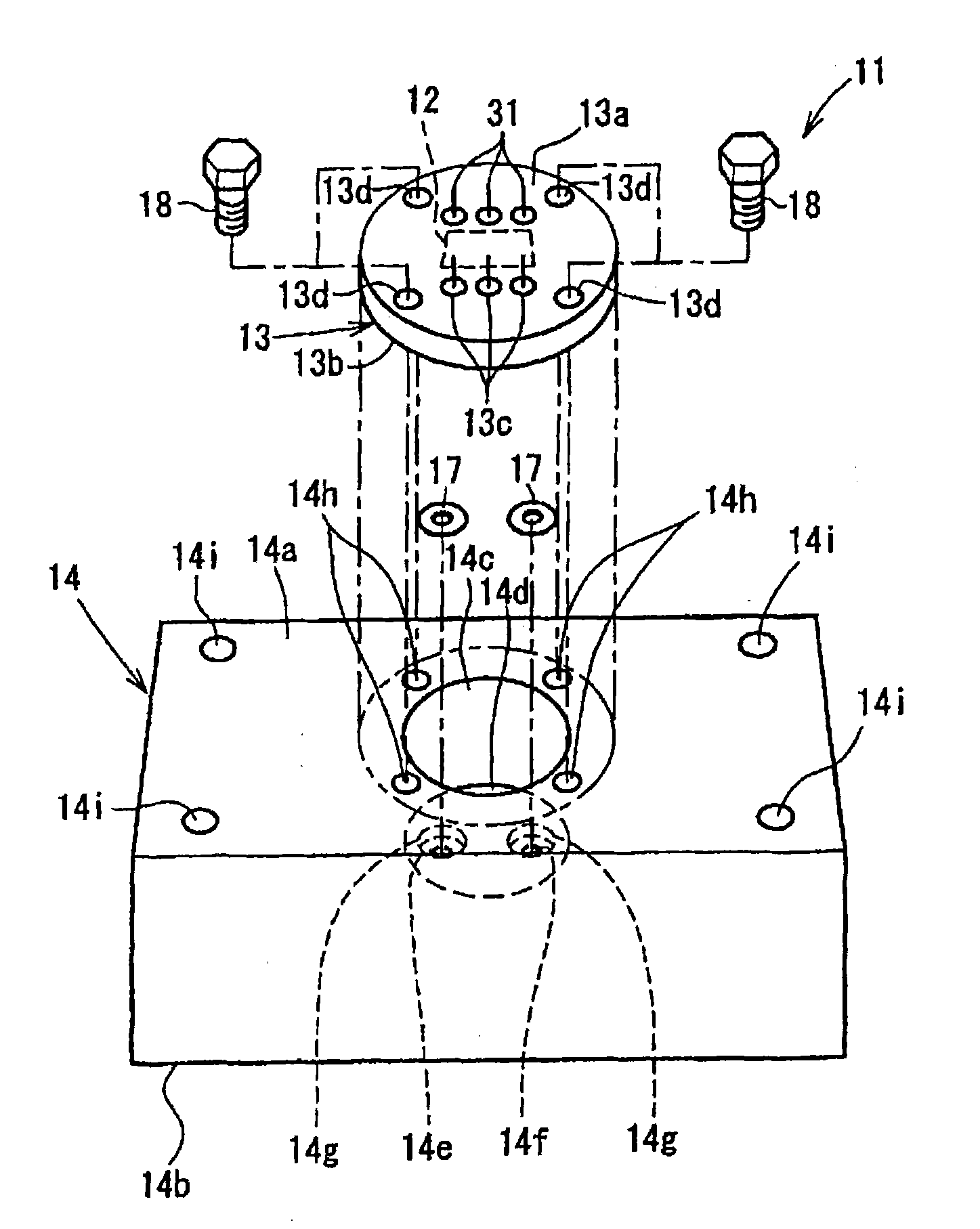
[0030] Hereinafter, a flow sensor unit according to one embodiment of the present invention will be described with reference to the drawings. figure 2 is an assembled perspective view of a flow sensor unit according to an embodiment of the present invention.

[0031] The flow sensor unit 11 is composed of the following components: a thermal flow sensor 12 indicated by a dotted line, which is used to detect the flow rate of the fluid to be measured; a mounting plate 13 made of metal, which is fixed on its lower surface (inner surface) and maintains the flow rate. sensor 12; and a flow channel body 14 made of metal, which is formed with a hole 14c for accommodating the flow sensor 12, a fluid introduction channel 14e, and a fluid discharge channel 14f, and the flow channel body 14 accommodates the flow sensor 12 and fixes the mounting plate 13 .

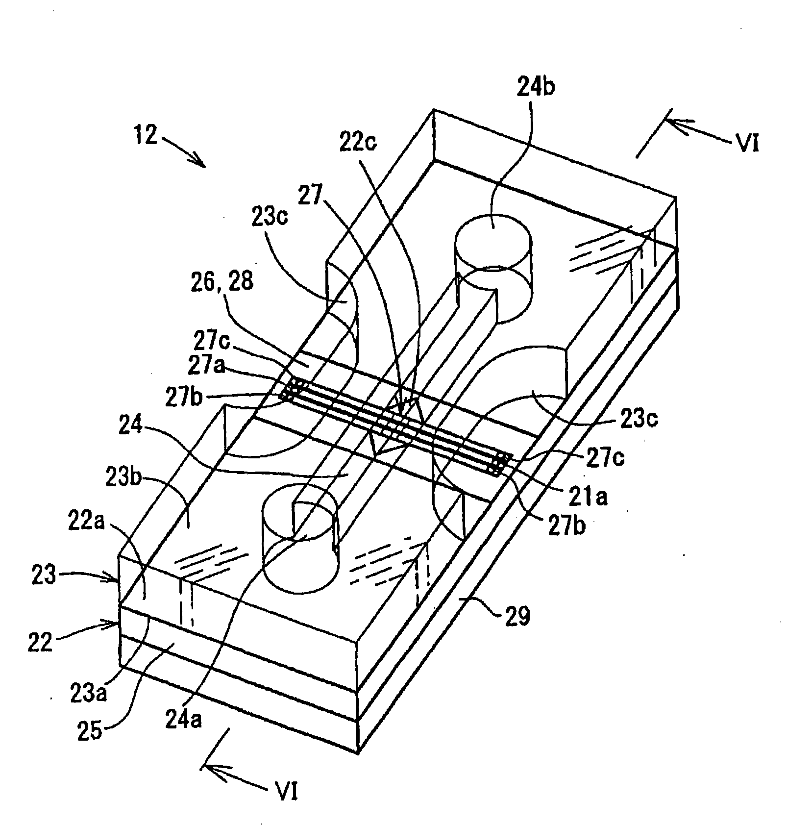
[0032] like image 3 As shown, the flow sensor 12 is composed of the following components: a flow sensor chip 22; a transparent gl...


PUM


Abstract

The present invention provides a flow sensor unit, including a flow sensor (12), provided with a sensor chip (22) and a flow channel forming component (23), wherein at least part of a concave portion on an upper surface of a substrate being covered by an insulating film, a flow rate detection portion (27) being formed on the insulating film, and a flow path forming member being arranged on the sensor chip and being provided with a flow path (24) of a fluid flowing through the flow rate detection portion; a metallic flow path body (14), accepting the flow sensor and provided with an accepting portion (14c) for accepting with a state that an inner circumference surface of the flow path body and an outer circumference surface of the flow sensor is separated with each other; a metallic mounting board (13), for fixing the flow sensor on the flow path body to accept the flow sensor in the flow path body accepting portion; and an insulating component (29), being inserted between the sensor chip of the flow sensor and the mounting board, and conjoining with the sensor chip as well as the mounting board.

Description

technical field [0001] The present invention relates to a flow sensor unit used in gas lines of semiconductor manufacturing equipment and the like, particularly in places requiring pressure resistance. Background technique [0002] For example, as a flow sensor (flow measuring device) for detecting the flow rate of a measured fluid such as a gas used in a semiconductor manufacturing device, it is known to measure a minute fluid by heating the fluid and measuring the temperature difference of the fluid at a predetermined position. The thermal flow sensor of flow rate (for example, refer to Japanese Patent Laid-Open No. 2002-168669 (5-6 pages, figure 1 ), Japanese Patent Laid-Open No. 2004-325335 (6-7 pages, Fig. 8)). [0003] figure 1 An example of a thermal flow sensor related to the present invention is shown. The thermal flow sensor 1 is formed by bonding a sensor chip 4 and a flow channel forming member (glass) 5. The sensor chip 4 is formed on a silicon substrate 2 wit...

Claims


Application Information

Patent Timeline
Patent Type & Authority Patents(China)
IPC IPC(8): G01F1/68
CPCG01F1/6845
Inventor 池信一上运天昭司熊佐淳司
Owner YAMATAKE HONEYWELL CO LTD
Why Eureka
Try Eureka