Flow sensor and manufacturing method therefor

A flow sensor and sensor chip technology, which is applied in the field of flow sensors, can solve the problems of poor alignment accuracy of flow sensors, increased manufacturing costs of flow sensors, and high cost of laser cutting devices, so as to achieve stability, product qualification rate, Effect of avoiding deterioration of measurement accuracy

Inactive Publication Date: 2011-02-02
YAMATAKE HONEYWELL CO LTD
View PDF3 Cites 0 Cited by
  • Summary
  • Abstract
  • Description
  • Claims
  • Application Information

AI Technical Summary

Problems solved by technology

However, the cost of the laser cutting device is very high, and the manufacturing cost of the flow sensor will also increase
In addition, even when a laser cutting device is used, in the process from separating the sensor chip 602 from the wafer 601 to bonding the glass chip to the sensor chip 602 , there is a possibility of adhesion on the flow detection part of the sensor chip 602 . dust
[0014] In addition, when Figure 3C As shown, when the upper surface of the separated sensor chip 602 is overlapped and separated into a single glass chip 604 and bonded, due to the positional deviation during bonding, fluctuations in the external dimensions will occur, and it is difficult to make the side surface of the flow sensor 605 605a coplanar, but will produce a step difference
When there is such a step difference, the dimensional tolerance of the chip outline will fluctuate, and the alignment accuracy of the flow sensor package will deteriorate.

Method used


Image

  • Flow sensor and manufacturing method therefor
  • Flow sensor and manufacturing method therefor
  • Flow sensor and manufacturing method therefor

Examples


no. 1 approach

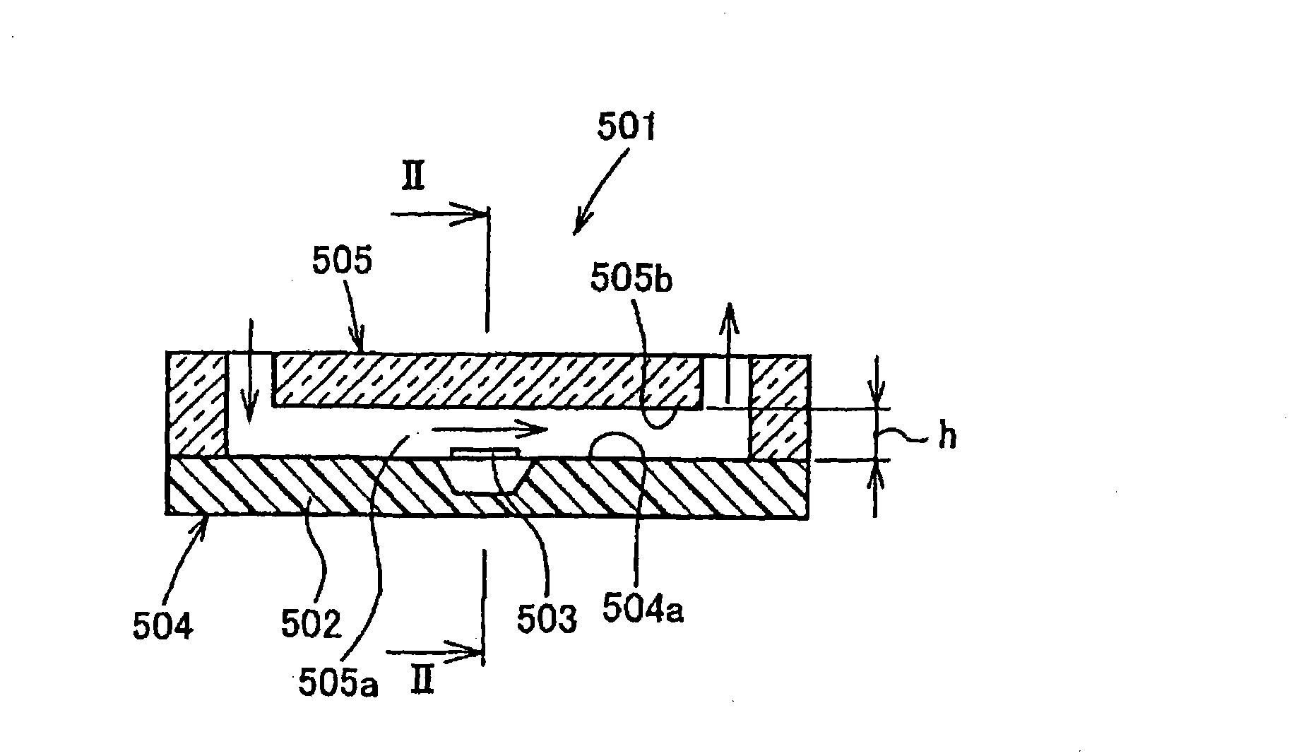
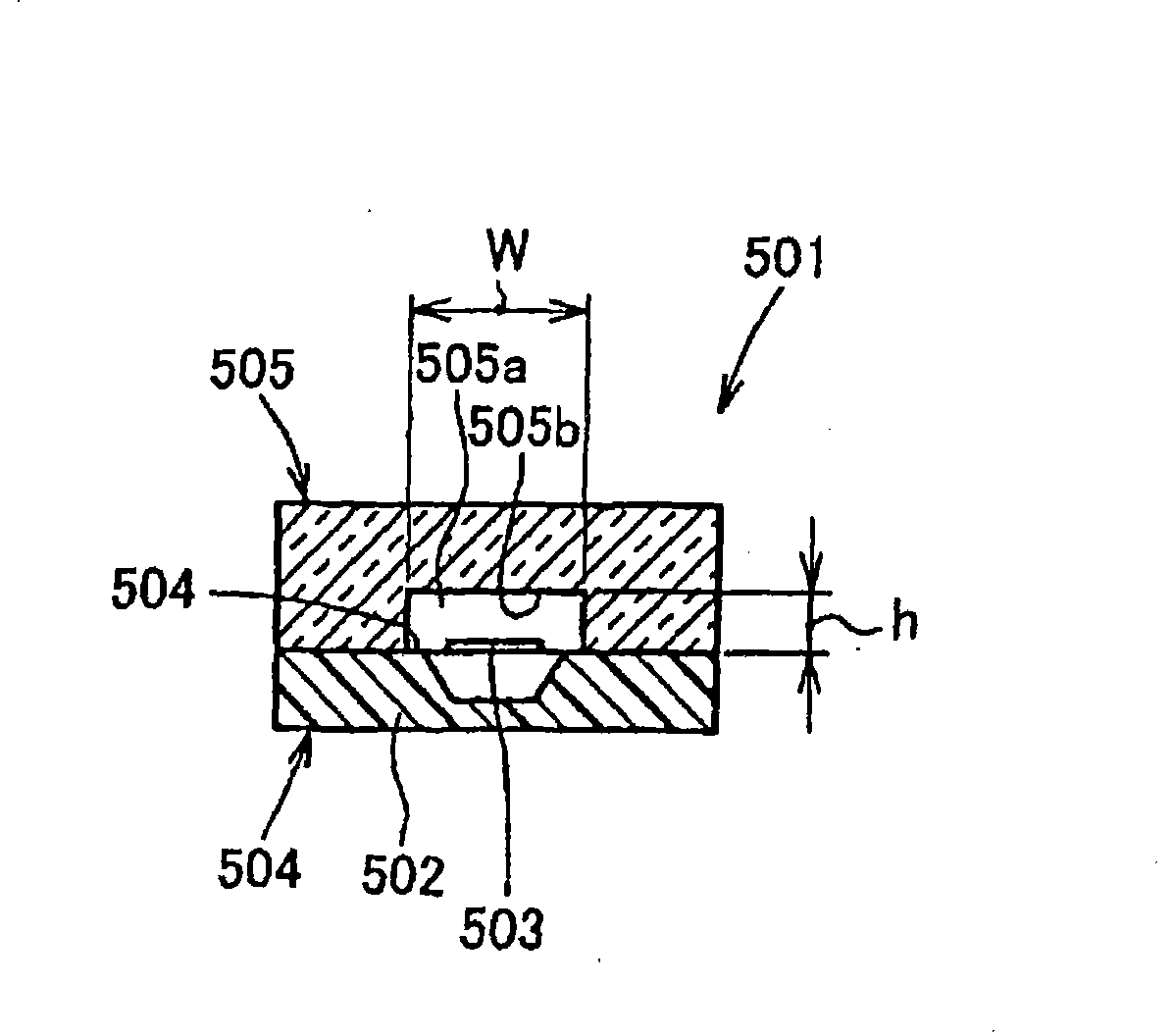
[0088] As described above, according to the first embodiment of the present invention, the transparent plate-shaped first flow path forming member and the second flow path forming member are joined together to form the flow path forming member, and the first flow path forming member is formed with The inlet hole and the outlet hole of the fluid; the above-mentioned second flow channel forming member is formed in a plate shape, and a through hole is arranged on it, and the through hole forms a flow channel along the flow of the fluid, and the fluid is arranged on the sensor chip along the flow through the flow detecting part, make the two ends of the through port (flow channel) communicate with the inlet hole and the outlet hole respectively, form a flow channel with a predetermined cross-sectional area of ​​the flow channel, and arrange the flow detecting part in the through port, thereby, can The height of the sensor flow path, that is, the cross-sectional area of ​​the throug...


PUM


Abstract

There is provided a flow sensor configured as described below. The flow sensor 11 is formed by bonding a sensor chip 12 formed with a flow rate detecting part 23 and a flow path forming member 15 that is provided on the sensor chip and is formed with a flow path for a fluid flowing in the flow rate detecting part to each other on the upper surface of a substrate 21. The flow path forming member is formed by bonding a transparent first flow path forming member 14 and a second flow path forming member 15 to each other. The first flow path forming member has a plate shape, and is provided with an inflow port 14c and a outflow port 14d for the fluid to be measured, and the second flow path forming member has a plate shape, and is provided with a through hole 15c that forms the flow path alongthe flow of the fluid flowing along.the flow rate detecting part. Both ends of the through hole communicate with the inflow port and the outflow port, and the flow rate detecting part is arranged in the through hole between the portions corresponding to the inflow port and the outflow port to form the flow path having a predetermined cross-sectional area, whereby the fabrication accuracy of the cross-sectional area of sensor flow path is enhanced, and thereby the flow rate detection accuracy is stabilized.

Description

technical field [0001] The present invention relates to a flow sensor suitable for measuring a minute flow rate of gas used in semiconductor manufacturing equipment, and a method for manufacturing the same. Background technique [0002] For example, as a flow sensor (flow measuring device) for detecting the flow rate of a fluid to be measured such as gas used in semiconductor manufacturing equipment, there is known a thermal flow sensor that measures the flow rate of the fluid at a predetermined position by heating the fluid To measure the tiny flow rate (for example, refer to Patent Document 1: Japanese Patent Application Laid-Open No. 2002-168669 (5-6 pages, figure 1 ); Patent Document 2: Japanese Patent Application Publication No. 2004-325335 (6-7 pages, Figure 8 ); Patent Document 3: Japanese Patent Application Publication No. 2007-071687 (2-3 pages, Figure 7 )). As described in Patent Document 3, a thermal flow sensor is composed of a sensor chip on which a flow de...

Claims


Application Information

Patent Timeline
Patent Type & Authority Patents(China)
IPC IPC(8): G01F1/684
Inventor 池信一畠山洋志土屋诚志
Owner YAMATAKE HONEYWELL CO LTD
Why Eureka
Try Eureka