
Linear vibrator and electronic equipment

A linear vibrator and vibrator technology, applied in the electronic field, can solve problems such as deviation of actual vibration performance of shrapnel, easy collision damage of permanent magnets, and deterioration of vibration performance, so as to reduce assembly differences and individual differences of shrapnel, ensure vibration performance, Eliminate the effect of collision damage

Pending Publication Date: 2021-01-22
东莞汉特斯电子科技有限公司
View PDF0 Cites 0 Cited by
  • Summary
  • Abstract
  • Description
  • Claims
  • Application Information

AI Technical Summary

Problems solved by technology

[0010] The purpose of the present invention is to provide a linear vibrator and electronic equipment, which overcomes the problems existing in the prior art that the permanent magnets are easily collided and damaged during over-vibration, resulting in degradation or even failure of the vibration performance, and the problems caused by the differences between the shrapnels. The deviation between the actual vibration performance and the theoretical design requirements

Method used


Image

  • Linear vibrator and electronic equipment
  • Linear vibrator and electronic equipment
  • Linear vibrator and electronic equipment

Examples


Embodiment Construction

[0056] In order to enable those skilled in the art to better understand the embodiments of the present application, the technical solutions in the embodiments of the present invention will be clearly and completely described below in conjunction with the drawings in the embodiments of the present invention. Obviously, the described implementation Examples are only some of the embodiments of the present invention, not all of them. Based on the embodiments in the embodiments of the present invention, all other embodiments obtained by persons of ordinary skill in the art without making creative efforts shall fall within the protection scope of the embodiments of the present invention.

[0057] In the embodiments of the present invention, the terms "comprising" and "having" and any variations thereof are intended to cover a non-exclusive inclusion, for example, a process, method, system, product or device comprising a series of steps or units is not necessarily limited to the expli...


PUM


Abstract

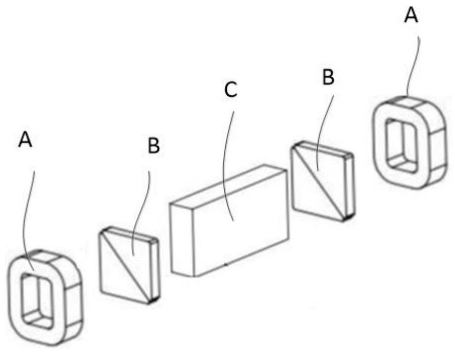
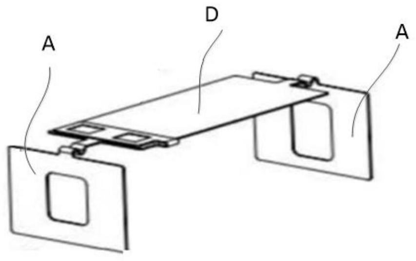
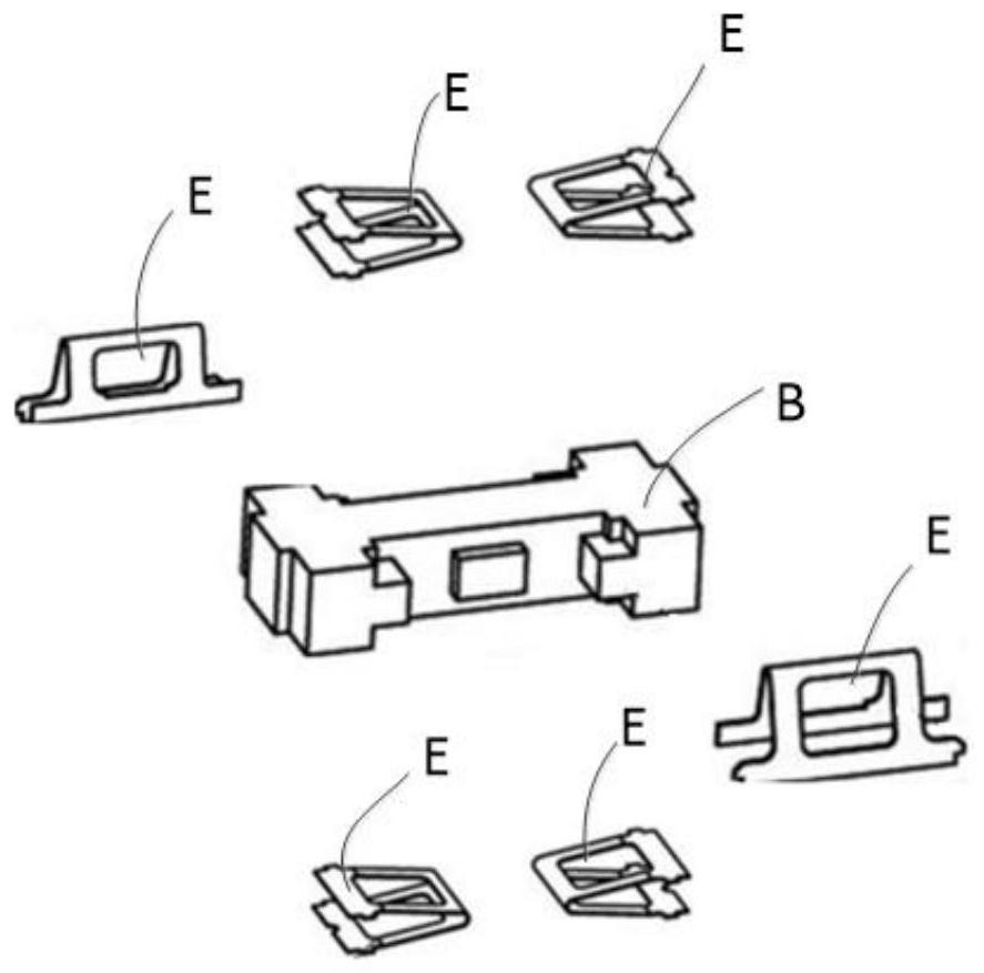
The invention relates to the technical field of electronics, and discloses a linear vibrator and electronic equipment. The linear vibrator comprises a vibration assembly and an elastic piece assembly,the vibration assembly comprises: a stator, which comprises a first permanent magnet and a second permanent magnet which are oppositely arranged at an interval, wherein magnetic field N areas and magnetic field S areas of the first permanent magnet and the second permanent magnet are divided along diagonal lines and are oppositely arranged; a vibrator, which is an electromagnet and is arranged between the two permanent magnets; a circuit board, which is arranged on the electromagnet and is electrically connected with the electromagnet; and an elastic sheet assembly, which comprises a bottom plate and two bending sheets with at least two bending parts, wherein the two bending sheets are respectively connected to two opposite side edges of the bottom plate, the two bending sheets and the bottom plate enclose to form a vibrator assembly space, in which the vibrator is arranged. According to the linear vibrator, the situation that the two permanent magnets are damaged due to collision iseradicated, and the vibration performance of the linear vibrator is ensured; the elastic sheet assembly difference and the individual difference are reduced to a large extent, and the assembly simplicity can be improved while the vibration performance machining precision is effectively improved.

Description

Technical field [0001] The present invention relates to the field of electronic technology, and in particular, to a linear vibrator and electronic equipment. Background technique [0002] Most of the traditional micro vibrators used for tactile feedback are realized by the vibration generated by the rotation of the eccentric wheel driven by a DC motor. Since the DC motor uses brush commutation, the service life of the traditional micro vibrator is limited by the brush, making it difficult to Breaking through 200 hours. [0003] Nowadays, there are micro brushless motor vibrators, which can replace the DC motor to drive the eccentric to rotate and generate vibration, which can solve the problem of life span. However, due to the long startup time, slow response speed and feedback delay, its application has been limited. limit. [0004] In addition, linear vibrators developed using the principle of linear motors only have a single resonance point when vibrating. However, the ...

Claims


Application Information

Patent Timeline
Patent Type & Authority Applications(China)
IPC IPC(8): H02K33/14H02K33/02
CPCH02K33/14H02K33/02
Inventor 阳政
Owner 东莞汉特斯电子科技有限公司
Learn More