Horizontal type spraying machine

A shotcrete machine, horizontal technology, applied in construction, building structure, processing of building materials, etc., can solve the problems of difficulty in entering concrete into the material cavity, increase the feeding time, reduce the work efficiency, etc., and shorten the material feeding. time, improve work efficiency, shorten the effect of feeding time

Inactive Publication Date: 2010-09-01
李卫平
View PDF7 Cites 0 Cited by
  • Summary
  • Abstract
  • Description
  • Claims
  • Application Information

AI Technical Summary

Problems solved by technology

The material cavity of this rotor type shotcrete machine is a circular tube material cavity. In order to prevent air leakage, the caliber of the existing circular tube material cavity is smaller than its height, which leads to a slow speed of feeding and discharging materials at the upper and lower openings of the circular tube. In order to ensure the concrete The slurry can fill the material cavity of the round tube in time, either reduce the volume of the material cavity to increase the feeding speed, or increase the feeding time to reduce the work efficiency; in addition, considering the volume of the whole machine, the diameter of the rotor cannot be made too large, Therefore, the diameter of the round tube material cavity is also restricted. The feed port of the circular tube material cavity is not very easy to be closed by the viscous concrete at the outlet of the hopper, resulting in the air in the circular tube material cavity cannot be discharged, making the concrete more difficult. Into the material cavity, the structural defect of the rotor material cavity causes the existing rotor type wet shotcrete machine to have low working efficiency and easy to block
In addition, the inlet and outlet ports are set on the sealing plate, and the leaked concrete slurry will easily enter between the sealing plate and the end face of the rotor material cavity during material feeding and discharging, which will aggravate the wear of the sealing plate. The existing shotcrete machine needs to frequently replace the sealing plate , and needs to be shut down for replacement, which is not conducive to construction and increases the cost of use

Method used


Image

  • Horizontal type spraying machine
  • Horizontal type spraying machine
  • Horizontal type spraying machine

Examples


Embodiment Construction

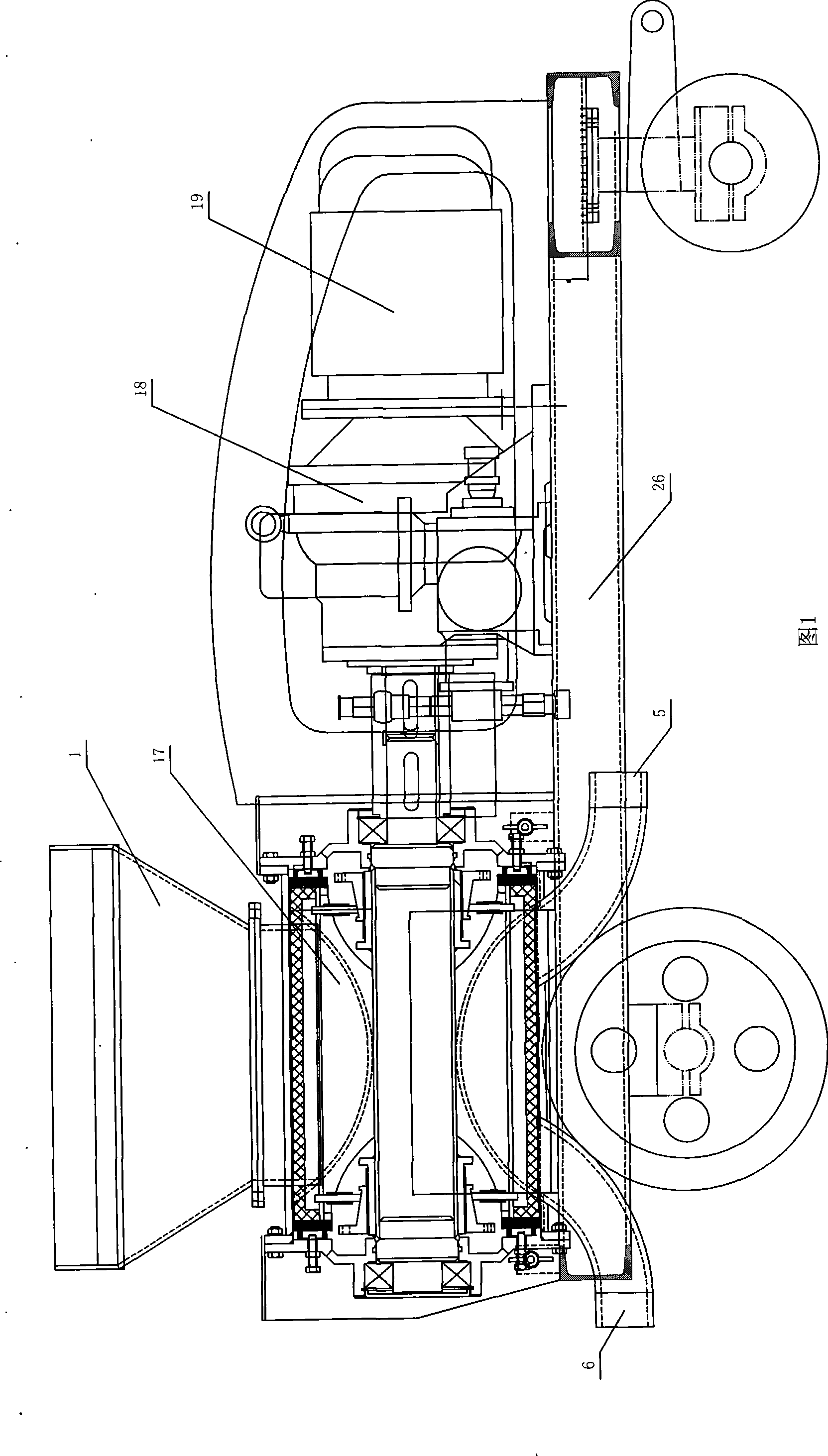
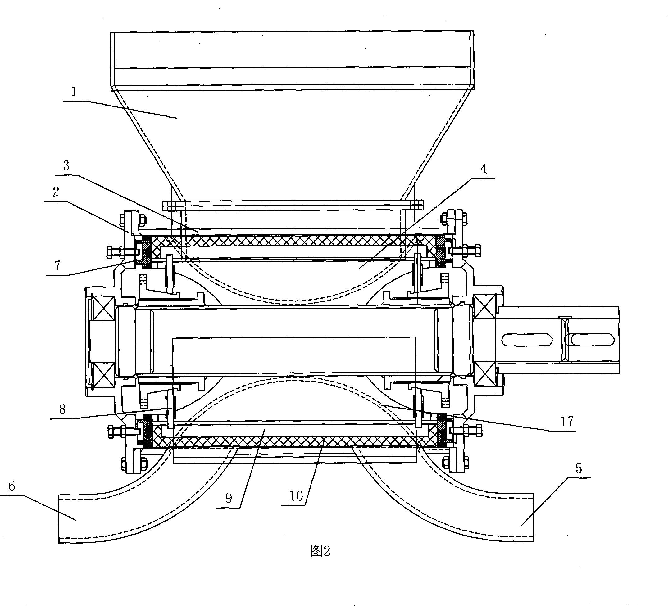
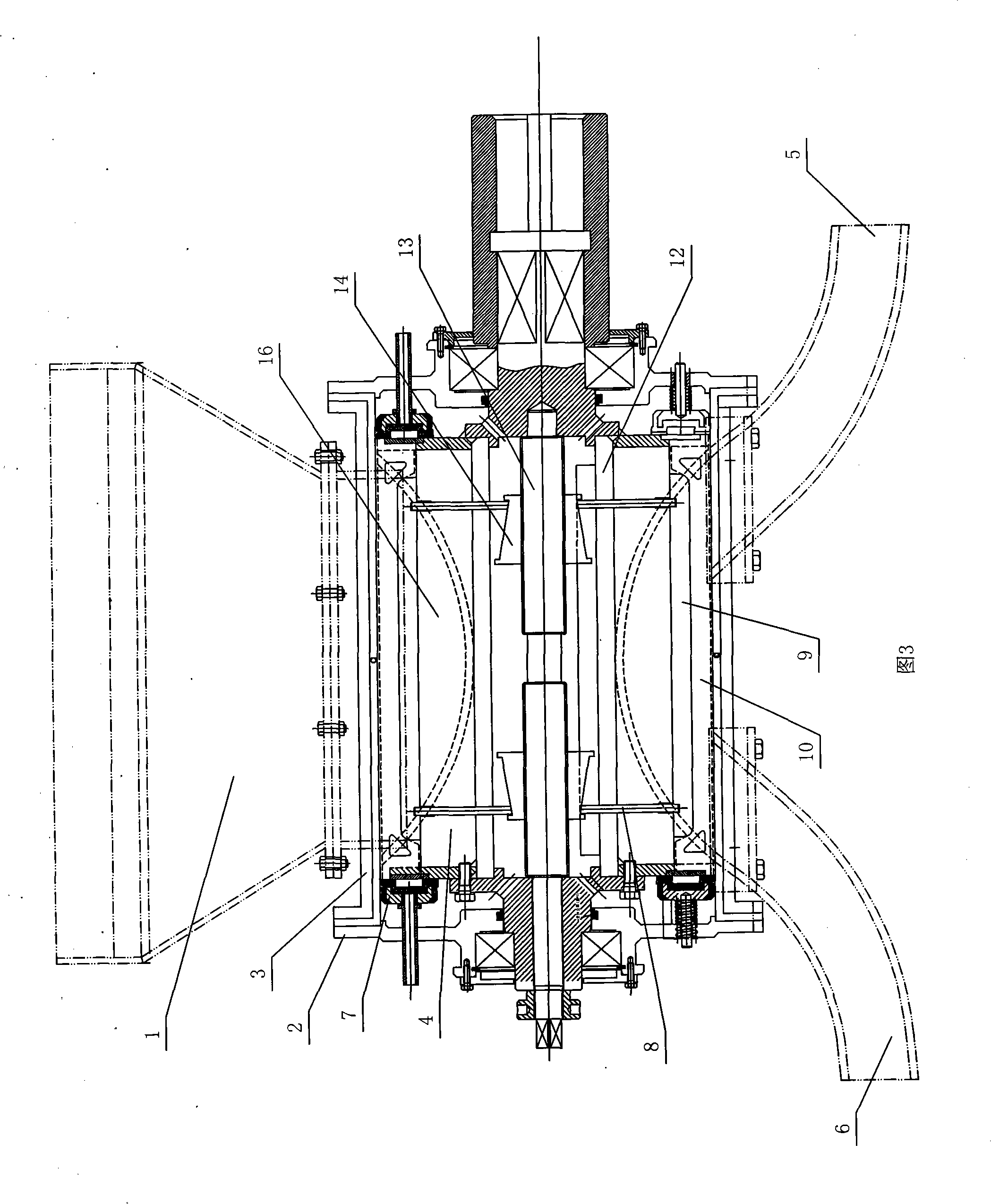
[0024] like figure 1 The shown horizontal shotcrete machine comprises a vehicle frame 26, a feeding host 17 and a hopper 1 arranged on the top of the feeding host 17, and the feeding host 17 includes a stator 3 and a rotor 4 arranged transversely on the frame 26, and the rotor 4 cylinders are provided with material grooves 16 at intervals; a hopper 1 is arranged above the stator 3, and the lower opening of the hopper 1 communicates with the inner cavity of the stator 3 and its position corresponds to the position of the material groove 16 on the rotor 4; The air inlet 5 and the air outlet 6 connected to the cavity and the opening position correspond to the position of the single material groove 16 on the rotor 4. The air inlet 5 communicates with the gas output port of the high-pressure gas generating device, and the rotor 4 shaft is connected to the air outlet through the reducer 18. The electric motor 19 is transmission connected.

[0025] A circumferential seal is provided...


PUM


Abstract

The invention discloses a horizontal sprayer which comprises a feeding host and a hopper arranged at the upper part of the feeding host, wherein the feeding host is composed of a framework and a rotor; a rotor shaft is connected with a power outputting device in a driving manner; the feeding host comprises a stator and the rotor which are horizontally arranged on the framework; material grooves are arranged on the circumference of the cylindrical surface of the rotor at intervals; a hopper is arranged above the stator; a lower opening of the hopper is communicated with a stator cavity and located corresponding to the position of the material grooves on the rotor; an air inlet and an air outlet which are communicated with the cavity are arranged below the stator, and the opening position is corresponding to the position of a single material groove on the rotor; the air inlet is communicated with an air outputting port of a high pressure gas generating device. The horizontal sprayer cancarry out an impulse-type continuous spraying operation, shorten the feeding time; the time interval for each spraying is short; and the maintenance is reduced and the work efficiency is improved.

Description

technical field [0001] The invention relates to a wet-process concrete spraying machine, in particular to a horizontal spraying machine. Background technique [0002] The feeding mechanism of the existing concrete rotor type wet spraying machine adopts a vertical structure, and the two ends of the rotor are provided with vertical through holes along the axial direction as the material cavity, and the upper and lower openings of the rotor material cavity are sealed by the upper and lower sealing plates. There is a feed port on the upper sealing plate corresponding to the position of the upper opening of the rotor material chamber, the upper part of the feeding port corresponds to the discharge port of the hopper, and the lower sealing plate has a discharge port corresponding to the caliber of the round pipe, and the discharge port is connected to the discharge port. The material pipe is also provided with an air inlet pipeline on the upper sealing plate directly above the dis...

Claims


Application Information

Patent Timeline
Patent Type & Authority Patents(China)
IPC IPC(8): E04G21/02
Inventor 李卫平朱明方
Owner 李卫平
Why Eureka
Try Eureka