Zooming projection lens

A technology of projection lens and lens group, which is applied in the field of zoom projection lens, can solve problems such as inability to effectively correct aberrations, focal power allocation mismatch, and back focus not meeting requirements, etc.

Inactive Publication Date: 2009-04-01
HONG FU JIN PRECISION IND (SHENZHEN) CO LTD +1
View PDF0 Cites 8 Cited by
  • Summary
  • Abstract
  • Description
  • Claims
  • Application Information

AI Technical Summary

Problems solved by technology

However, changing the position of the mirror group will change the optical power of the zoom projection lens, which may lead to: (1) resolution degradation (the optical power distribution does not match, and aberrations cannot be effectively corrected); (2) for accommodating projection devices (such as The back focal length (the distance from the last optical surface of the zoom projection lens to the surface of the SLM) of various polarizing devices of LCD projectors and LCoS projectors) does not meet the requirements; Telecentric imaging requirements (so that the screen can receive a clear projected picture within a certain distance)

Method used


Image

  • Zooming projection lens
  • Zooming projection lens
  • Zooming projection lens

Examples


Embodiment 1

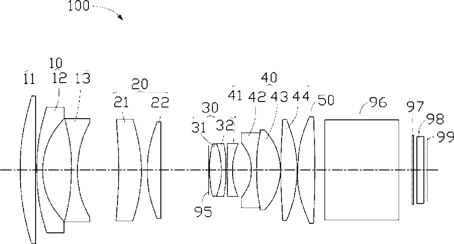
[0062] The zoom projection lens 100 of Embodiment 1 satisfies the conditions listed in Table 1 and Table 2, and F1=-28.8377 millimeters (Millimeter, mm), F2=33.0414mm, F3=40.8227mm, F4=-141.6108mm, F5=49.8472 mm.

[0063] Table 1

[0064] surface R(mm) D(mm) Nd vd The surface of the magnifying end of the first lens 79.971 5.035 1.6451 55.8878 first lens reducing end surface -998.751 0.15 - - Second lens magnifying end surface 67.492 1.8 1.5569 64.1644 Second lens reducing end surface 23.691 8.847 - - The surface of the magnifying end of the third lens -65.086 1.8 1.5994 54.9599 The surface of the third lens reducing end 31.281 D6 (refer to Table 2) - - The surface of the magnifying end of the fourth lens -161.501 6.962 1.744 44.8511 The surface of the fourth lens reducing end -51.457 1.83 - - The surface of the magnifying end of the fifth lens 40.839 4.456 1.7491 34.8735 Re...

Embodiment 2

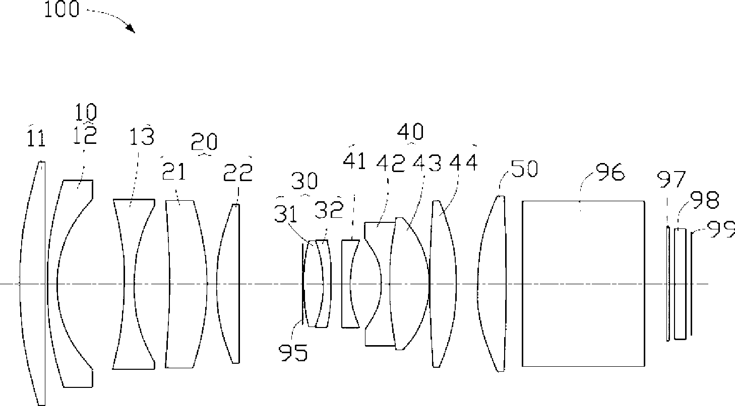
[0070] The zoom projection lens 100 of Embodiment 2 satisfies the conditions listed in Table 3 and Table 4, and F1=-29.3527mm, F2=33.8755mm, F3=40.6828mm, F4=-152.5071mm, F5=51.142mm.

[0071] table 3

[0072] surface R(mm) D(mm) Nd vd The surface of the magnifying end of the first lens 82.072 4.916 1.7023 48.5664 first lens reducing end surface -1344.621 0.17 - - Second lens magnifying end surface 63.239 1.8 1.5131 67.7652 Second lens reducing end surface 22.918 8.968 - - The surface of the magnifying end of the third lens -64.557 1.8 1.6315 50.4312 The surface of the third lens reducing end 32.077 D6 (refer to Table 4) - - The surface of the magnifying end of the fourth lens -153.501 7 1.6807 50.9542 The surface of the fourth lens reducing end -49.356 0.17 - - The surface of the magnifying end of the fifth lens 40.843 4.391 1.7306 31.8018 Reduced end surface of the fifth le...

Embodiment 3

[0078] The zoom projection lens 100 of Embodiment 3 satisfies the conditions listed in Table 5 and Table 6, and F1=-28.0963mm,

[0079] F2=33.3390mm, F3=40.5215, F4=-182.3747mm, F5=53.1237mm.

[0080] table 5

[0081] surface R(mm) D(mm) Nd vd The surface of the magnifying end of the first lens 79.997 4.758 1.6879 50.1164 first lens reducing end surface -4583.001 0.353 - - Second lens magnifying end surface 60.664 1.8 1.5382 65.5839 Second lens reducing end surface 22.373 8.82 The surface of the magnifying end of the third lens -67.588 1.8 1.6376 56.2887 The surface of the third lens reducing end 31.666 D6 (refer to Table 6) - - The surface of the magnifying end of the fourth lens -144.43 7 1.6885 50.0393 The surface of the fourth lens reducing end -46.511 0.17 - - The surface of the magnifying end of the fifth lens 40.133 4.371 1.7346 34.607 Reduced end surface of the fif...


PUM


Abstract

The invention provides a zooming projection lens, which, from magnification end to reduction end, sequentially comprises a first lens group with negative focal power, a second lens group with positive focal power, a third lens group with positive focal power, a fourth lens group with negative focal power and a fifth lens group with positive focal power; the zooming projection lens meets the formula as follows: F1 / Fw is less than -1.3 and more than -1.5; F2 / Fw is less than 1.8 and more than 1.5; F3 / Fw is less than 2.2 and more than 1.8; F4 / Fw is less than -5 and more than -10; F5 / Fw is less than 2.8 and more than 2.3; wherein, F1, F2, F3, F4 and F5 are respectively the effective focal distance of the first lens group, the second lens group, the third lens group, the fourth lens group and the fifth lens group; Fw is the shortest effective focal distance of the zooming projection lens.

Description

technical field [0001] The invention relates to projection technology, in particular to a zoom projection lens. Background technique [0002] At present, digital light processing (Digital Light Processing, DLP) projectors, liquid crystal display (Liquid Crystal Display, LCD) projectors using liquid crystal light valves (Lightvalve), and silicon crystal (Liquid Crystal on Silicon, LCoS) projectors have replaced cathode projectors. Tube (Cathode Ray Tube, CRT) projectors have become mainstream products in the market. In the past, CRT projectors can correct the aberration of the zoom projection lens through electrical compensation (electrically compensation), while DLP, LCD and LCoS projectors do not have the ability of electrical compensation, so it is required to be applied to DLP, LCD or LCoS projectors The projection lens has the ability to optically correct aberrations to obtain high-quality projection images. [0003] With the development of semiconductor technology, th...

Claims


Application Information

Patent Timeline
Patent Type & Authority Applications(China)
IPC IPC(8): G02B15/177G02B15/16G02B9/60
CPCG02B15/177G02B15/145523
Inventor 林群翎黄俊翔李崇
Owner HONG FU JIN PRECISION IND (SHENZHEN) CO LTD
Why Eureka
Try Eureka