Power transmission control device, power transmitting device, non-contact power transmission system, and secondary coil positioning method

A technology of secondary coils and control devices, which is applied in the direction of circuit devices, electromagnetic wave systems, battery circuit devices, etc., and can solve the problem that power transmission devices cannot actively obtain coils, etc.

Active Publication Date: 2009-04-01
CHAMIRAUX MANAGEMENT LLC
View PDF2 Cites 31 Cited by
  • Summary
  • Abstract
  • Description
  • Claims
  • Application Information

AI Technical Summary

Problems solved by technology

[0007] In the technology of Patent Document 2, although the position adjustment (alignment) of the primary coil and the secondary coil can be correctly presented to the user, since the position deviation is determined based on the output of the rectifier circuit in the power receiving device, the It is necessary to continuously transmit power from the power transmitting device to the power receiving device, and the power transmitting device cannot actively obtain information on the positional deviation between the coils

Method used


Image

  • Power transmission control device, power transmitting device, non-contact power transmission system, and secondary coil positioning method
  • Power transmission control device, power transmitting device, non-contact power transmission system, and secondary coil positioning method
  • Power transmission control device, power transmitting device, non-contact power transmission system, and secondary coil positioning method

Examples


no. 1 example

[0055] First, an application example of a contactless power transmission system to which the present invention is applied will be described.

[0056] (Application example of non-contact power transmission system)

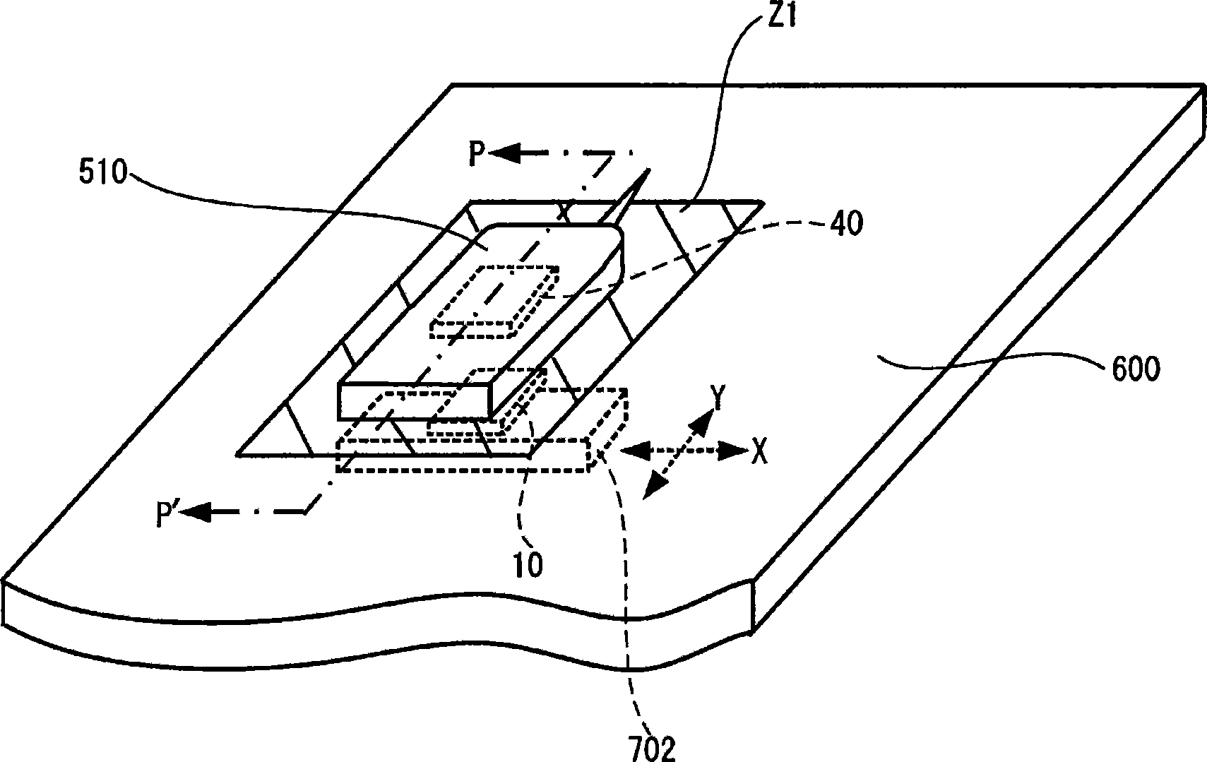
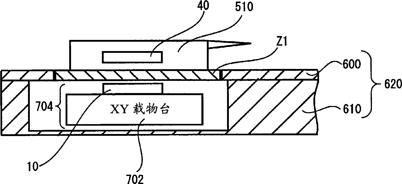
[0057] FIG. 1(A) and FIG. 1(B) are diagrams showing an example of an application method of the non-contact power transmission system according to the present invention. FIG. 1(A) is a perspective view of the system equipment, and FIG. 1(B) is a cross-sectional view along line P-P' of the system equipment of FIG. 1(A).

[0058] As shown in FIG. 1(B), the power transmission side device 704 (primary side structure having the power transmission device 10 of the present invention, an actuator (not shown), and an XY stage 702) is built in a flat Inside the planar structure (here, system equipment) 620 .

[0059] That is, the power transmission-side device 704 is installed in a recess formed inside the system device 620 . On the upper portion of the system device 620 , ...

no. 2 example

[0176] In this embodiment, the scanning mechanism using the primary coil of the actuator is not provided on the primary side. Position adjustment between the two coils is performed by the user manually moving the secondary-side device. Below, it demonstrates concretely.

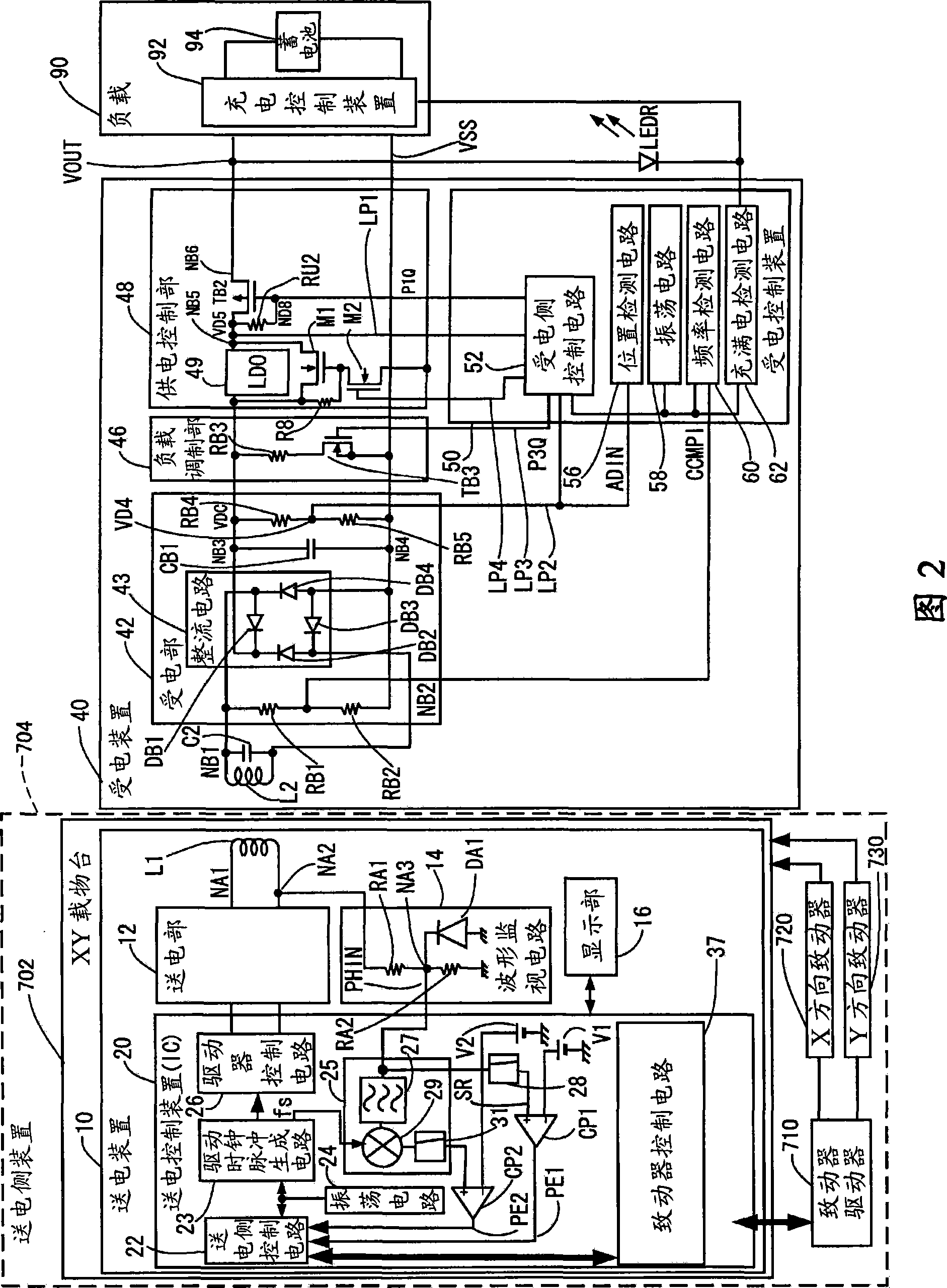
[0177] Figure 17 It is a diagram showing another configuration of the power transmission device (a configuration for detecting the proximity of the secondary-side device and notifying the relative positional relationship information of the two coils). Although Figure 17 The main components of Figure 4 same, but in Figure 17 neutralize Figure 4 The difference is that the actuator control circuit 37 is not provided, and a display control unit 39 is provided instead of the actuator control circuit 37 .

[0178] which is, Figure 17 The power transmission device 10 (power transmission control device 20) has only the function of displaying the detection result (relative positional relationship informatio...

no. 3 example

[0192] In the above-mentioned embodiment, although the approach detection circuit (28, CP1) of the harmonic detection circuit 25 and the secondary coil is used as a method for adjusting the positional relationship between the primary coil (L1) and the secondary coil (L2) Although it has been explained, these circuits also have a function of detecting (determining) whether or not an article on the loading area ( Z1 ) can be an object of power transmission if the point of view is changed.

[0193] That is, the detection of harmonics by the harmonic detection circuit 25 indicates that what is placed on the mounting area is not a screw or a nail, but a secondary-side device that can be a power transmission target (at least there is a possibility). That is, the harmonic detection circuit 25 also functions as means for detecting whether an item placed on the loading zone ( Z1 ) is a device that can be a power transmission target (a detector for whether it is an appropriate secondary-...


PUM


Abstract

The invention discloses power transmission control device, power transmission device, non-contact power transmission system and secondary coil positioning method. The power transmission device (primary side device) can automatically detect relative position relation between the power transmission device (primary side device) and the power receiving side device (secondary side device) in high accuracy. The power transmission control device (20) includes a power-transmitting-side control circuit (22) that controls power transmission to a power receiving device (40), and a harmonic detection circuit (25) that detects a harmonic signal of a drive frequency of a primary coil. A resonant circuit (leakage inductance and resonant capacitor C2) that resonates with the harmonic of the drive frequency of the primary coil L1 is formed in the power receiving device (40) so that harmonic resonance occurs.

Description

technical field [0001] The invention relates to a power transmission control device, a power transmission device, a non-contact power transmission system, a secondary coil positioning method and the like. Background technique [0002] In recent years, contactless power transmission (non-contact power transmission), which utilizes electromagnetic induction and enables power transmission even when metal parts are not in contact, has attracted attention. As examples of application of this contactless power transmission, charging of mobile phones and home appliances (for example, handsets of telephones and watches) has been proposed. [0003] For example, Patent Document 1 describes a non-contact power transmission device using a primary coil and a secondary coil. [0004] In addition, Patent Document 2 describes a technique for detecting a positional deviation (offset) between a primary coil and a secondary coil in a non-contact power transmission system. In the technology de...

Claims


Application Information

Patent Timeline
Patent Type & Authority Applications(China)
IPC IPC(8): H02J17/00H02M3/28
CPCH02J7/025H02J5/005H02J7/00045H02J50/80H02J50/90H02J50/60H02J50/12H02J50/70
Inventor 神干基
Owner CHAMIRAUX MANAGEMENT LLC
Why Eureka
Try Eureka