

Control device for air conditioner
A technology for air conditioners and control devices, applied in air conditioning systems, heating and ventilation control systems, instruments, etc., can solve the problems of reducing user convenience, inconveniently checking various changes in working conditions, and not being able to easily check working conditions, etc.
- Summary
- Abstract
- Description
- Claims
- Application Information
AI Technical Summary
Problems solved by technology
Method used
Image

Examples
Embodiment Construction
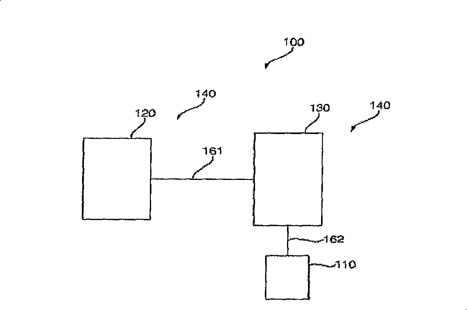
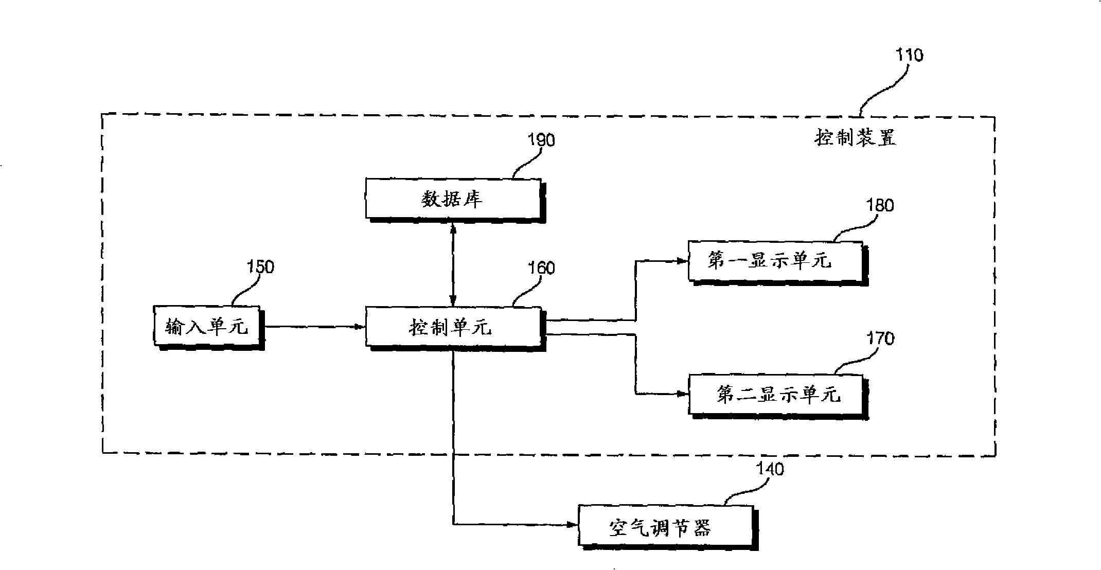
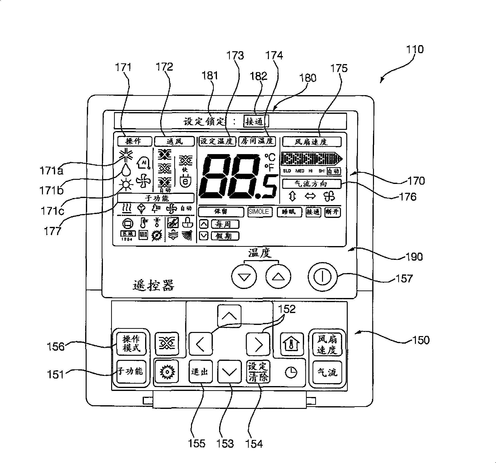
[0022] figure 1 is a block diagram showing the configuration of the air conditioning system 100 having the control device 110 according to one embodiment of the present invention. figure 2 is shown as figure 1 A block diagram of the flow of control signals in the air conditioning system 100 is shown. image 3 is like figure 1 A schematic plan view of the control device 110 is shown. Figure 4 is shown in image 3 A plan view of the status of selecting the "Operation Mode" item in the display unit.
[0023] refer to figure 1 , the air conditioning system 100 includes an air conditioner 140 and a remote controller 110 . The air conditioner 140 includes an indoor unit 130 disposed in an indoor space and an outdoor unit 120 disposed in an outdoor space. The indoor unit 130 and the outdoor unit 120 are communicatively connected to each other via the network 161 . Although the air conditioner 140 includes one outdoor unit 120 and one indoor unit 130, the present invention i...
PUM
 Abstract
Description
Claims
Application Information