Apparatus and method of measuring workpieces

A technology for components and sensing equipment, applied in the direction of measuring devices, instruments, etc., can solve problems such as being unsuitable for larger, not always feasible, etc.

Active Publication Date: 2009-04-08
RENISHAW PLC
View PDF1 Cites 14 Cited by
  • Summary
  • Abstract
  • Description
  • Claims
  • Application Information

AI Technical Summary

Problems solved by technology

[0006] The method of scanning features such as drilled holes has the disadvantage that it is not suitable for larger holes (i.e. if the radius of the hole is larger than the probe length) or very small holes
Furthermore, this scanning method is not always feasible due to accessibility constraints

Method used


Image

  • Apparatus and method of measuring workpieces
  • Apparatus and method of measuring workpieces
  • Apparatus and method of measuring workpieces

Examples


Embodiment Construction

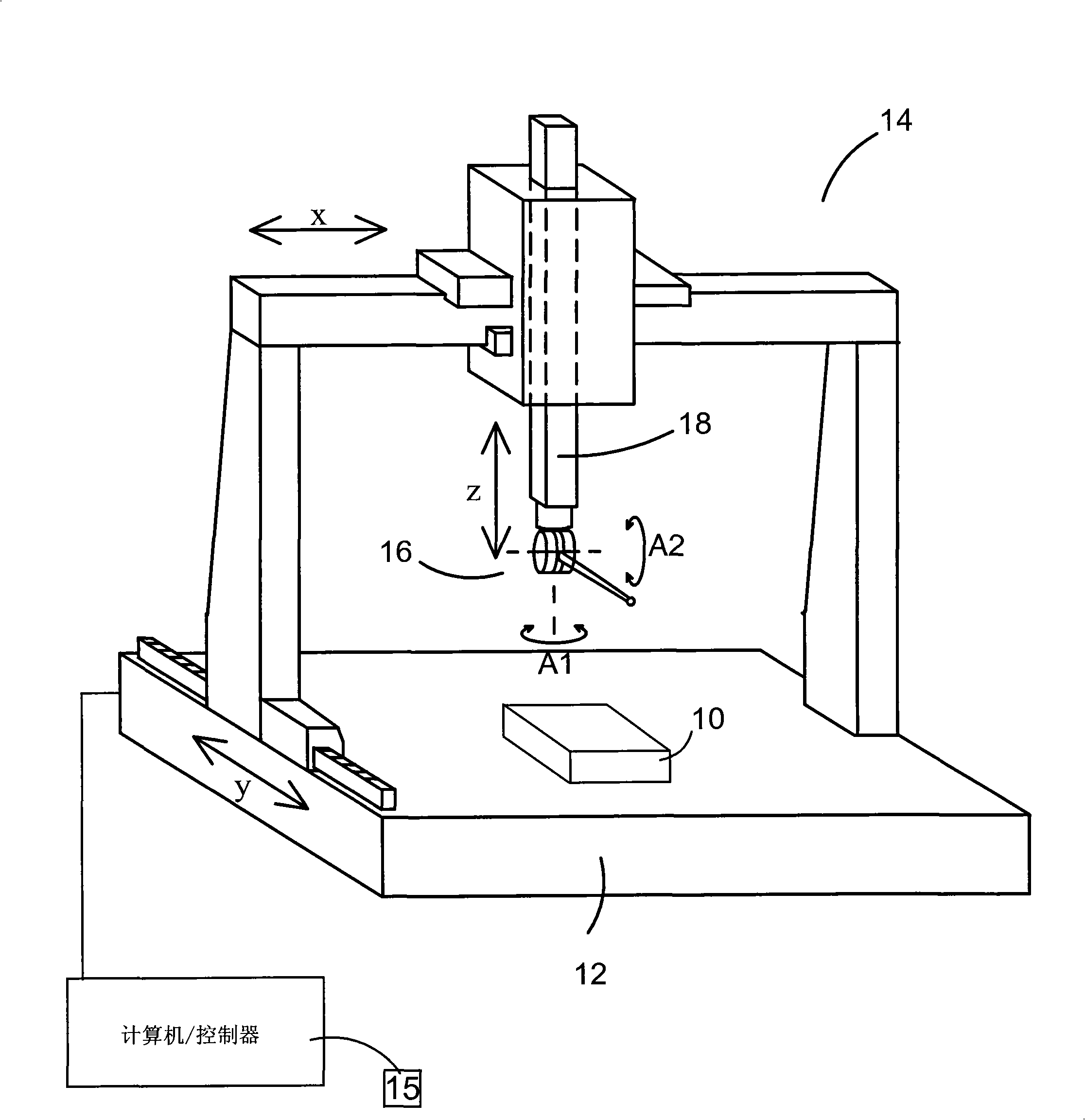
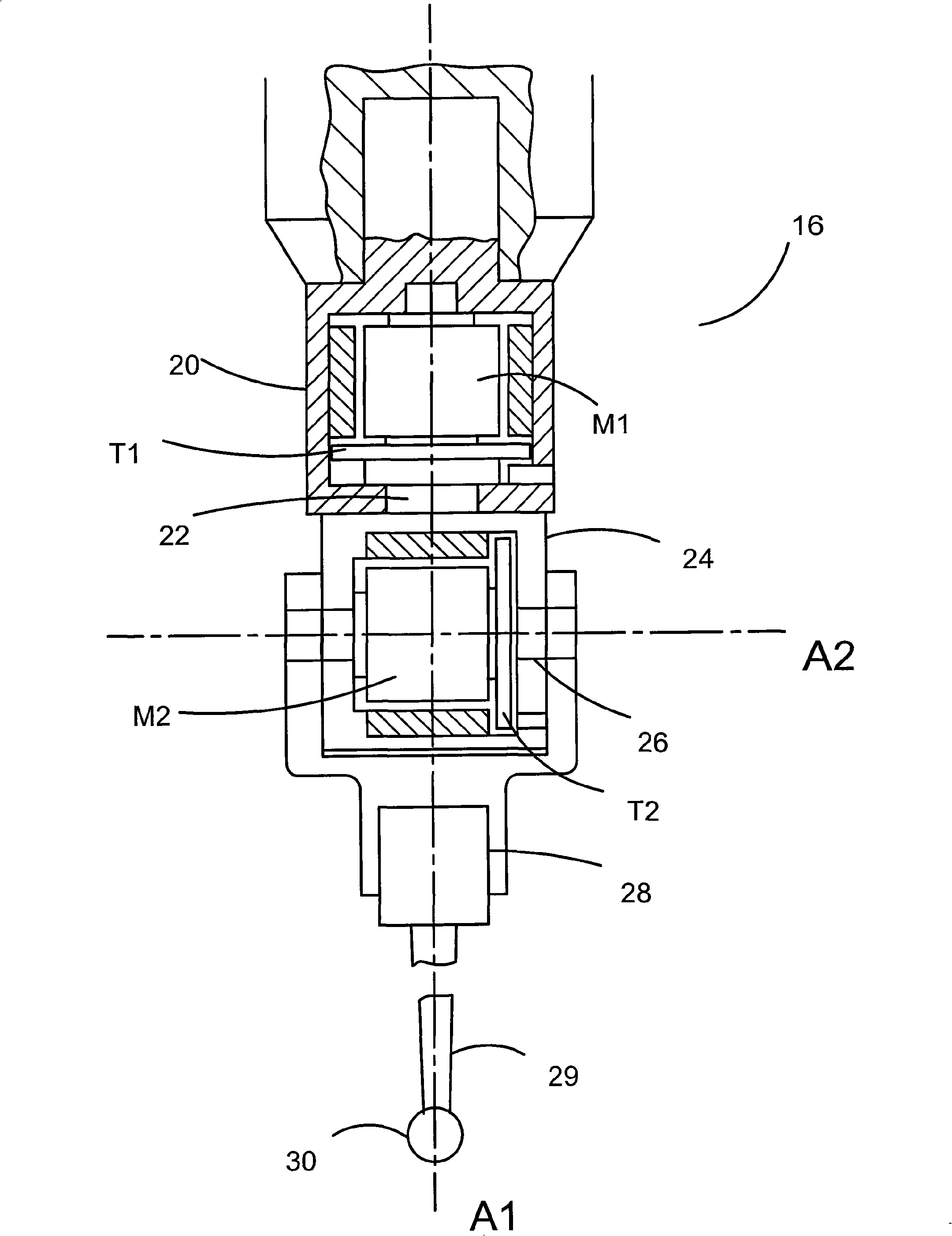
[0037] figure 1 A motorized scanning head is shown mounted on a coordinate measuring machine (CMM). The workpiece to be measured is mounted on the table 12 of the CMM 14 and the motorized scanning head 16 is mounted on the spindle 18 of the CMM 14 . The mandrel can be driven in the X, Y, Z directions relative to the table by means of a motor in a known manner. Such as figure 2 As shown, the motorized scanning head 16 comprises a stationary part formed by a base or housing 20 supported by a moving part in the form of a shaft 22 which is rotatable about an axis A1 relative to the housing 20 . The shaft 22 is fixed to a further housing 24 which in turn supports a shaft 26 which can be rotated relative to the housing 24 by a motor M2 about an axis A2 perpendicular to the axis A1 .

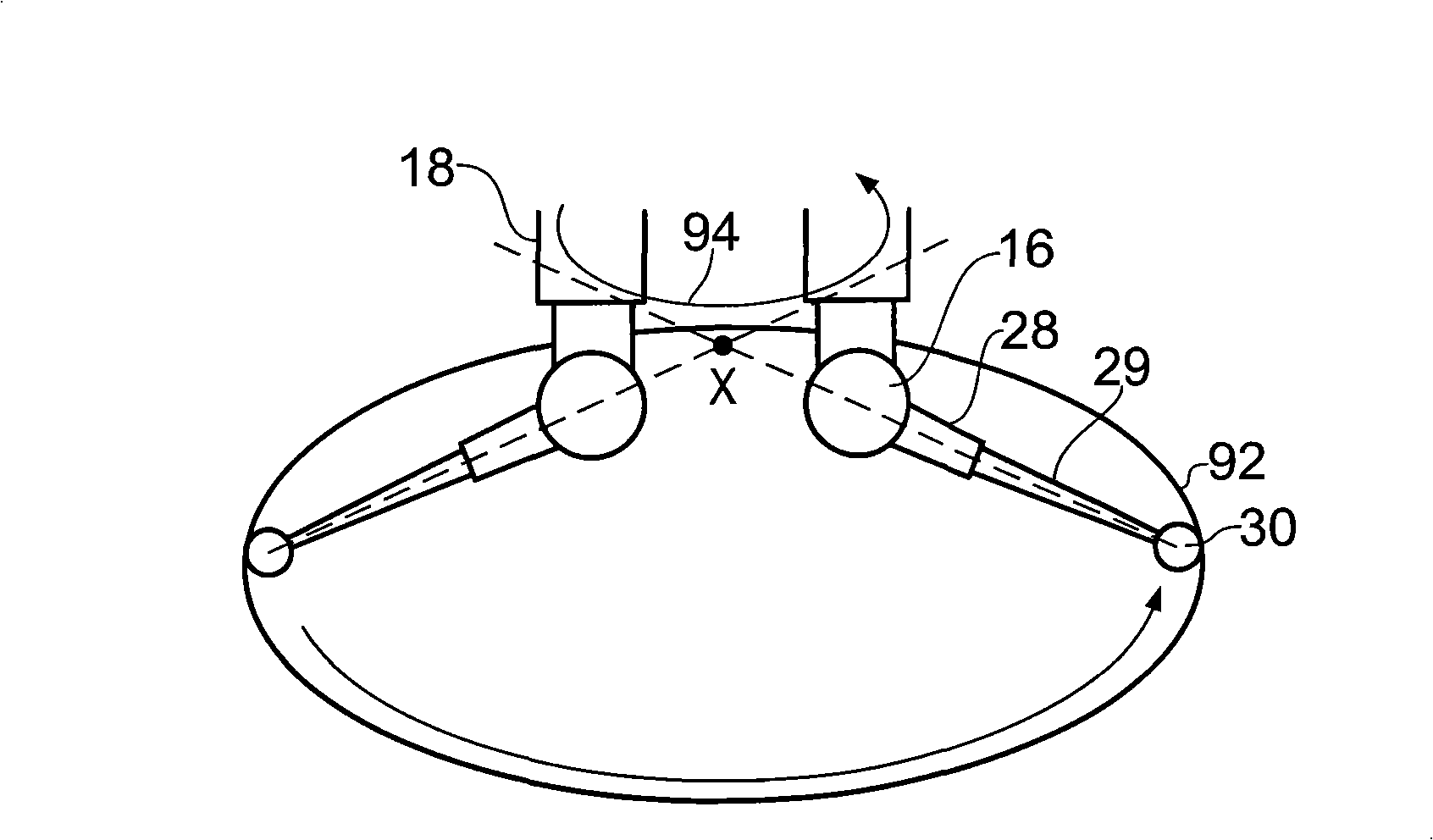
[0038] A probe 28 with a probe 29 having a workpiece contact tip 30 is mounted to the motorized scanning head. This arrangement allows the head's motors M1, M2 to angularly position the workpiece ...


PUM


Abstract

A method and apparatus for measuring a surface using a surface sensing device mounted on a scanning head on a member of a coordinate positioning apparatus. The coordinate positioning apparatus may be operated to produce relative movement between the scanning head and the surface profile and the scanning head includes a drive for producing rotational movement of the surface sensing probe about oneor more axis. A desired measurement profile on the surface which the surface sensing device will track and the desired motion of the orientation of the surface sensing device as the surface' sensing device follows the measurement profile are defined. This data is used to derive the required path of the relative motion between the member of the coordinate positioning apparatus and the surface, such that the surface sensing device prescribes a trajectory along the measurement profile.

Description

technical field [0001] The present invention relates to a method of measuring the surface of a workpiece using a motorized scanning head mounted on a coordinate positioning device such as a coordinate measuring machine (CMM), a machine tool, a manual coordinate measuring arm, and an inspection robot. Background technique [0002] It is known from International Patent Application Publication WO 90 / 07097 to mount a motorized scanning head on a coordinate measuring machine. The motorized scan head allows a probe mounted on the motorized scan head to rotate about two nominally orthogonal axes. The probe can be positioned angularly with respect to these two axes, while the motorized scanning head can be positioned anywhere within the working volume of the instrument by means of a sit positioner. [0003] This motorized scan head provides a coordinate positioner with greater scanning flexibility because the motorized scan head can position the probe in many different orientations...

Claims


Application Information

Patent Timeline
Patent Type & Authority Applications(China)
IPC IPC(8): G01B21/04
CPCG01B21/04
Inventor 史蒂文·保罗·亨特若弗雷·麦克法兰凯维恩·巴里·乔纳斯哈立德·马穆尔
Owner RENISHAW PLC
Why Eureka
Try Eureka