
Electric adjusting apparatus of tool holder

A technology for adjusting devices and knife holders, which is applied in printing, rotary printing machines, printing machines, etc., can solve problems such as low work efficiency and inaccurate position adjustment, and achieve the effect of improving work efficiency and ensuring precision

Inactive Publication Date: 2011-06-22
QINGDAO ZANGNAN PAPER PROD MACHINERY
View PDF0 Cites 0 Cited by
  • Summary
  • Abstract
  • Description
  • Claims
  • Application Information

AI Technical Summary

Problems solved by technology

[0003] The purpose of the present invention is to provide a new type of electric adjustment device for knife rests in view of the inaccurate position adjustment and low work efficiency of existing knife rest adjustment devices

Method used


Image

  • Electric adjusting apparatus of tool holder
  • Electric adjusting apparatus of tool holder
  • Electric adjusting apparatus of tool holder

Examples


Embodiment Construction

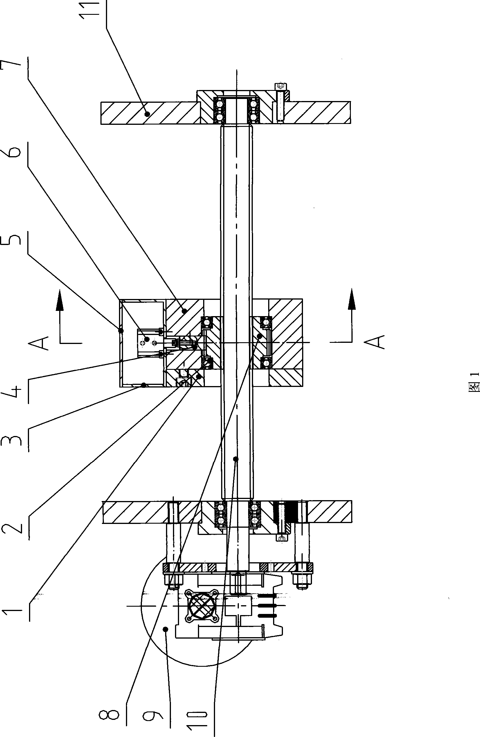
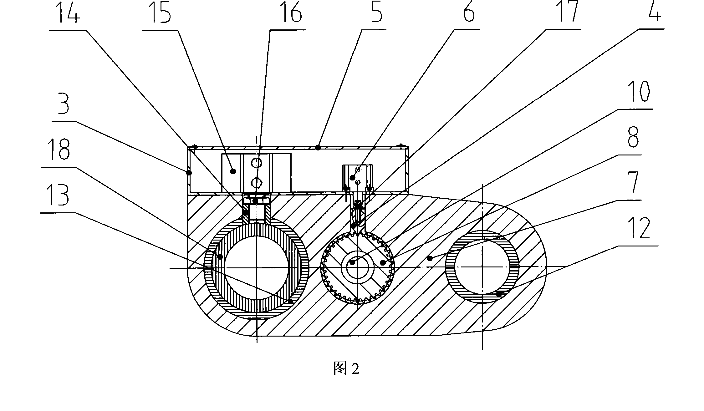
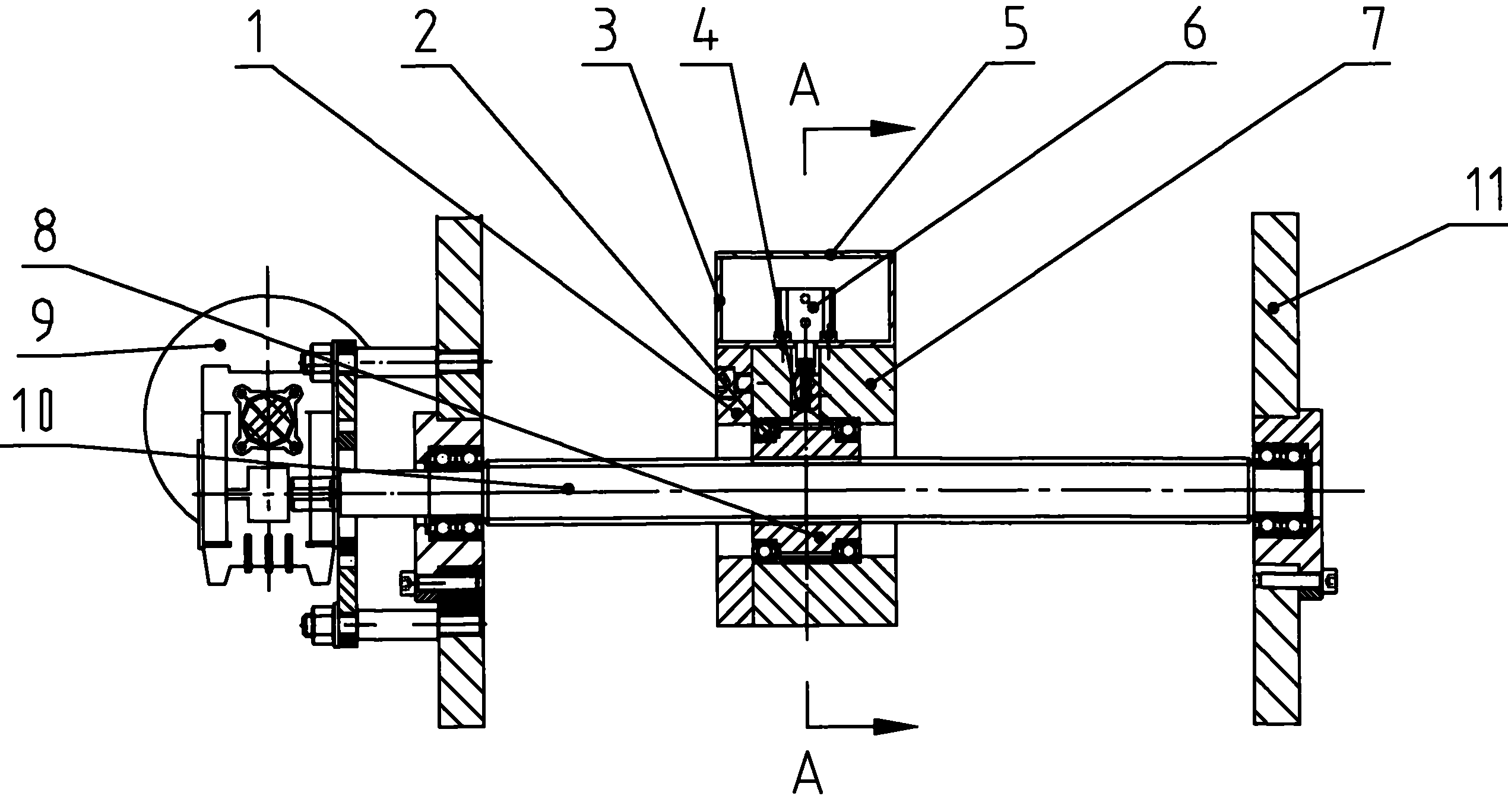
[0013] like figure 1 and figure 2 The specific embodiment of the present invention shown is a kind of tool post electric adjustment device, which includes wallboards 11 at both ends, a lead screw 10 installed between the wallboards 11, and a lead screw 10 installed on the outside of one end wallboard. Linked reducer 9, lead screw 10 is provided with a knife rest 7, inside the said knife rest 7 is provided with a gear 8 set on the lead screw 10, between the knife rest 7 and gear 8 is provided with a rolling bearing 2, the The outer edge of the gear 8 is provided with meshing teeth. The top of knife rest 7 is provided with cylinder 6, and the bottom of cylinder 6 utilizes nut 17 to be connected with a stop shaft 4, and stop shaft 4 is positioned at gear 8 directly above. A first guide shaft 18 and a second guide shaft 12 are also arranged between the wallboards 11 at the two ends, and a matching guide shaft hole is provided inside the knife rest 7; the periphery of the first ...


PUM


Abstract

The invention relates to a tool rest electric adjusting device, which comprises wall boards on the two ends of the tool rest electric adjusting device, a leading screw arranged between the wall boards, and a decelerator arranged outside the wall board on one end of the device and linked with the leading screw, wherein the leading screw is provided with the tool rest, the inside of the tool rest is provided with a gear sleeved on the leading screw, an outer edge of the gear is provided with an engaged tooth, the top end of the tool rest is provided with an air cylinder, the bottom of the air cylinder is connected with a stop shaft, and the stop shaft is positioned right above the gear. Because the tool rest and the gear form the adjusting device through the leading screw for adjustment, and the leading screw and the stop shaft of the gear are electrically controlled, the axial adjustment of the tool rest can be achieved without manual operations, thus the working efficiency is greatly improved and the adjusting accuracy is guaranteed.

Description

technical field [0001] The invention relates to a device for adjusting the axial movement of a knife rest in a printing machine, in particular to a device for adjusting the position of the knife rest in an electric manner. Background technique [0002] At present, in printing machinery, the axial movement adjustment of the knife rest adopts a mechanical adjustment device composed of a rack and an adjustment gear shaft. The multiple knife rests on the equipment are respectively realized by an adjustment structure. When adjusting the position, the staff It is necessary to use a special wrench to insert into the adjusted hole, and apply a large force to move the tool holder to the required position one by one. However, in this way, it is difficult to ensure the accuracy of the adjustment position, and the work efficiency is greatly reduced, which cannot meet the needs of automatic production. Contents of the invention [0003] The purpose of the present invention is to provi...

Claims


Application Information

Patent Timeline
Patent Type & Authority Patents(China)
IPC IPC(8): B41F13/56
Inventor 丁仁喜张忠柏丁曰丰
Owner QINGDAO ZANGNAN PAPER PROD MACHINERY
Learn More