
Array detecting device

An array testing, to-be-tested technology, applied in the direction of measuring devices, measuring electricity, measuring electrical variables, etc., can solve problems such as power consumption

Inactive Publication Date: 2009-04-29
TOP ENG CO LTD
View PDF1 Cites 7 Cited by
  • Summary
  • Abstract
  • Description
  • Claims
  • Application Information

AI Technical Summary

Problems solved by technology

Therefore, unnecessary power may be consumed when the panel is tested for defects

Method used

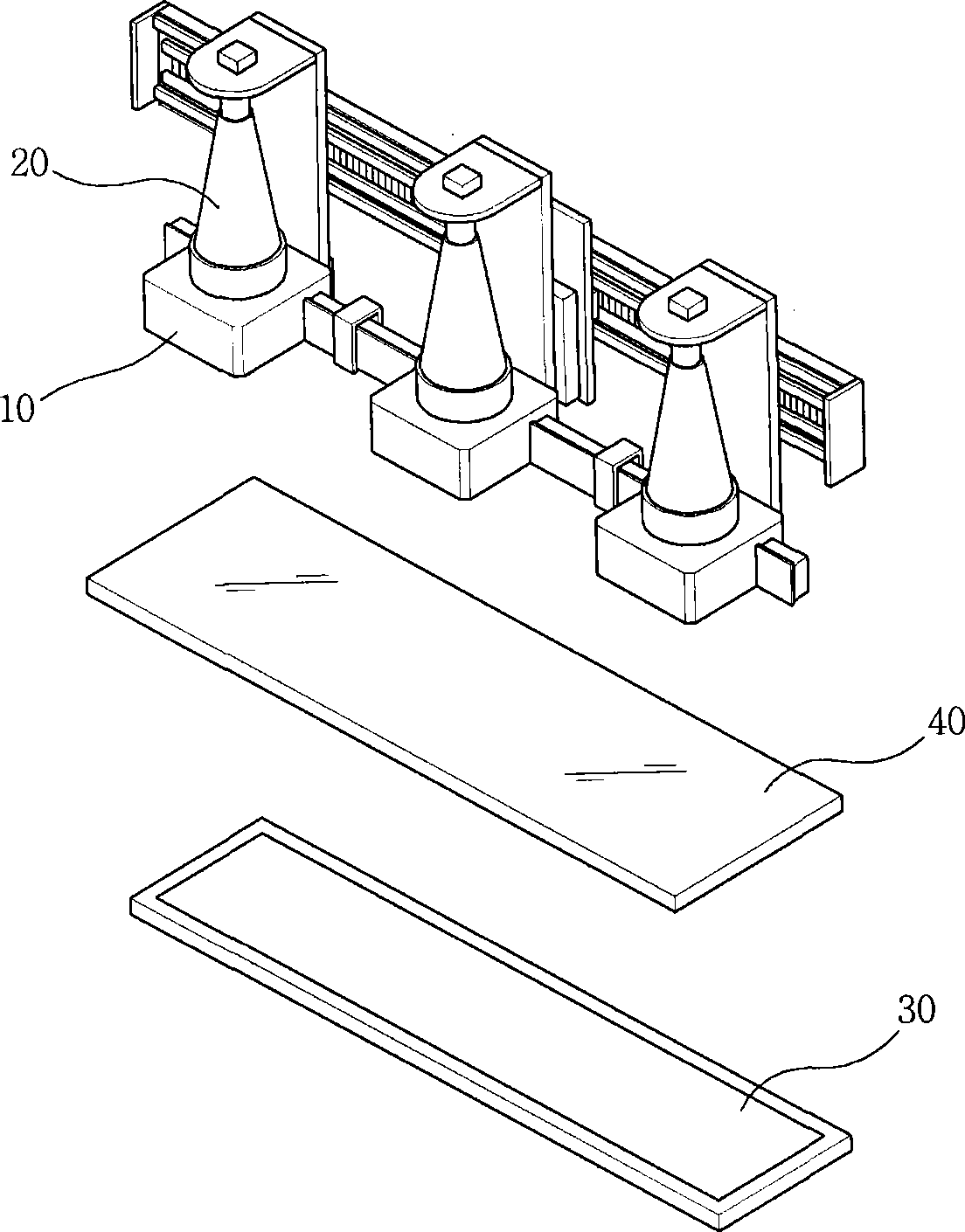

Image

  • Array detecting device
  • Array detecting device
  • Array detecting device

Examples


Embodiment Construction

[0020] The following detailed description is provided to assist the reader in gaining a comprehensive understanding of the methods, apparatus and / or systems described herein. Accordingly, various changes, modifications, and equivalents to the systems, apparatus, and / or methods described herein will occur to those skilled in the art. Also, descriptions of well-known functions and constructions are omitted for increased clarity and conciseness.

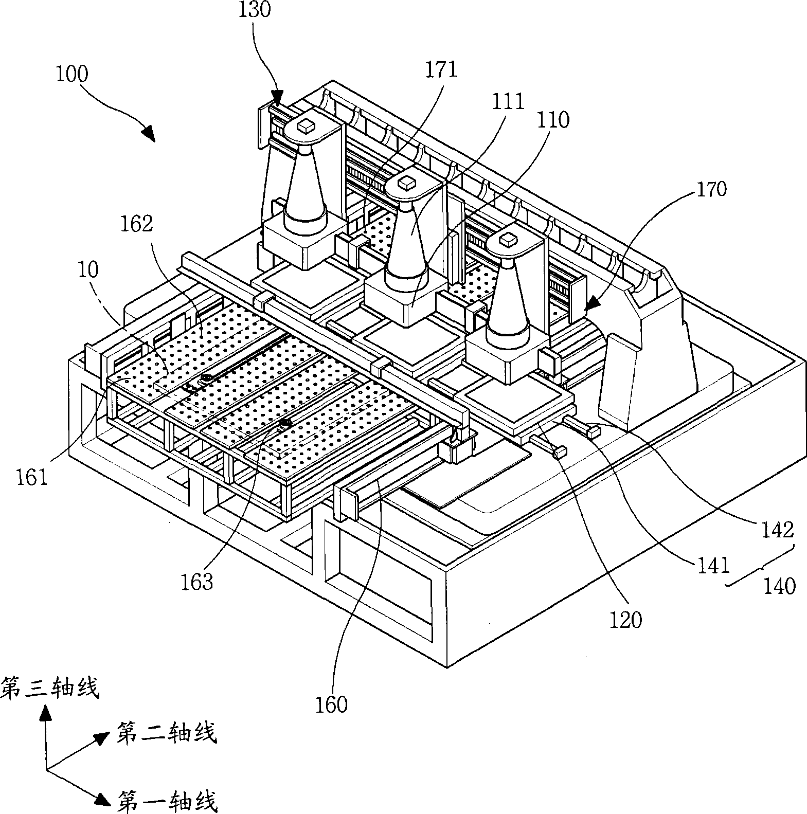
[0021] figure 2 is a perspective view of an array testing device 100 according to an exemplary embodiment. refer to figure 2 , the array testing device 100 includes a plurality of modulators 110 and a plurality of light sources 120 .

[0022] Each modulator 110 is arranged on one side of the substrate 10 to be tested ( figure 2 The upper part of the substrate 10 in). The modulator 110 moves along a first axis. The first axis is perpendicular to the direction of movement of the substrate 10 towards the modulator 110 . The modul...


PUM


Abstract

The invention discloses an array test apparatus that detects whether electric defect exists in a plurality of electrodes on the substrate of the display panel. The array test apparatus comprises at least one light source and at least one modulator. The light source is installed at one side of the substrate opposite to the position where the modulation is installed. The light source is corresponding to the modulator, which emits light to the corresponding modulator and is moved to a position that is the same as that of the modulator. The size of the light source is as small as that of the modulator, so the luminance difference of the light source is obviously reduced. Therefore, the light source emits uniform light to the substrate to provide uniform light for the modulator so that the amount of light changed according to whether defects exist in the electrode of the panel can be stable. Therefore, a detection unit for testing array measures the amount of the light through the modulator and whether the electrode has defects is accurately ensured so that the reliability of detecting defects by the panel.

Description

[0001] Related application reference [0002] This application claims priority from Korean Patent Application No. 10-2008-0076203 filed on Aug. 4, 2008, the disclosure of which is hereby incorporated by reference in its entirety. technical field [0003] The following description relates to an array testing device that detects electrical defects in a plurality of electrodes disposed on a substrate of a display panel. Background technique [0004] The array test device is a device for detecting defects in electrodes on a substrate of a display panel. The display panel includes flat panel display devices such as a liquid crystal display (LCD), a plasma display panel (PDP), and an organic light emitting diode (OLED). The array testing device can test whether there is a defect in electrodes disposed on a thin film transistor (TFT) substrate of an LCD panel. A general TFT LCD panel includes a TFT substrate, a color substrate on which color filters and common electrodes are form...

Claims


Application Information

Patent Timeline
IPC IPC(8): G02F1/1362G02F1/13G01R31/00
CPCB65G49/063G02F1/1309G09G3/006
Inventor 潘俊浩丁东澈崔渊圭方圭龙张文柱
Owner TOP ENG CO LTD
Learn More