Method and system for controlling gas turbine

A gas turbine and engine technology, applied in the direction of gas turbine devices, combustion methods, machines/engines, etc., can solve problems such as reducing hardware life

Active Publication Date: 2009-05-06
GENERAL ELECTRIC CO
View PDF0 Cites 9 Cited by
  • Summary
  • Abstract
  • Description
  • Claims
  • Application Information

AI Technical Summary

Problems solved by technology

Thus, the additional cycles incurred reduce hardware life, requi

Method used


Image

  • Method and system for controlling gas turbine
  • Method and system for controlling gas turbine
  • Method and system for controlling gas turbine

Examples


Embodiment Construction

[0017] The following detailed description illustrates the content of the present invention by way of example and not limitation. This detailed description clearly enables one skilled in the art to make and use the present disclosure, which describes several embodiments, modifications, variations, alternatives, and uses of the present disclosure, including the present What is believed to be the best mode of carrying out the teachings of the invention. The teachings of the present invention are described as applied to a preferred embodiment, a method of delivering fuel in a gas turbine engine. However, it is contemplated that the teachings of the present invention are also generally applicable to equipment having other combustion devices in addition to fuel delivery to equipment having burners, such as, but not limited to, furnaces, boilers, kilns, and incineration furnace.

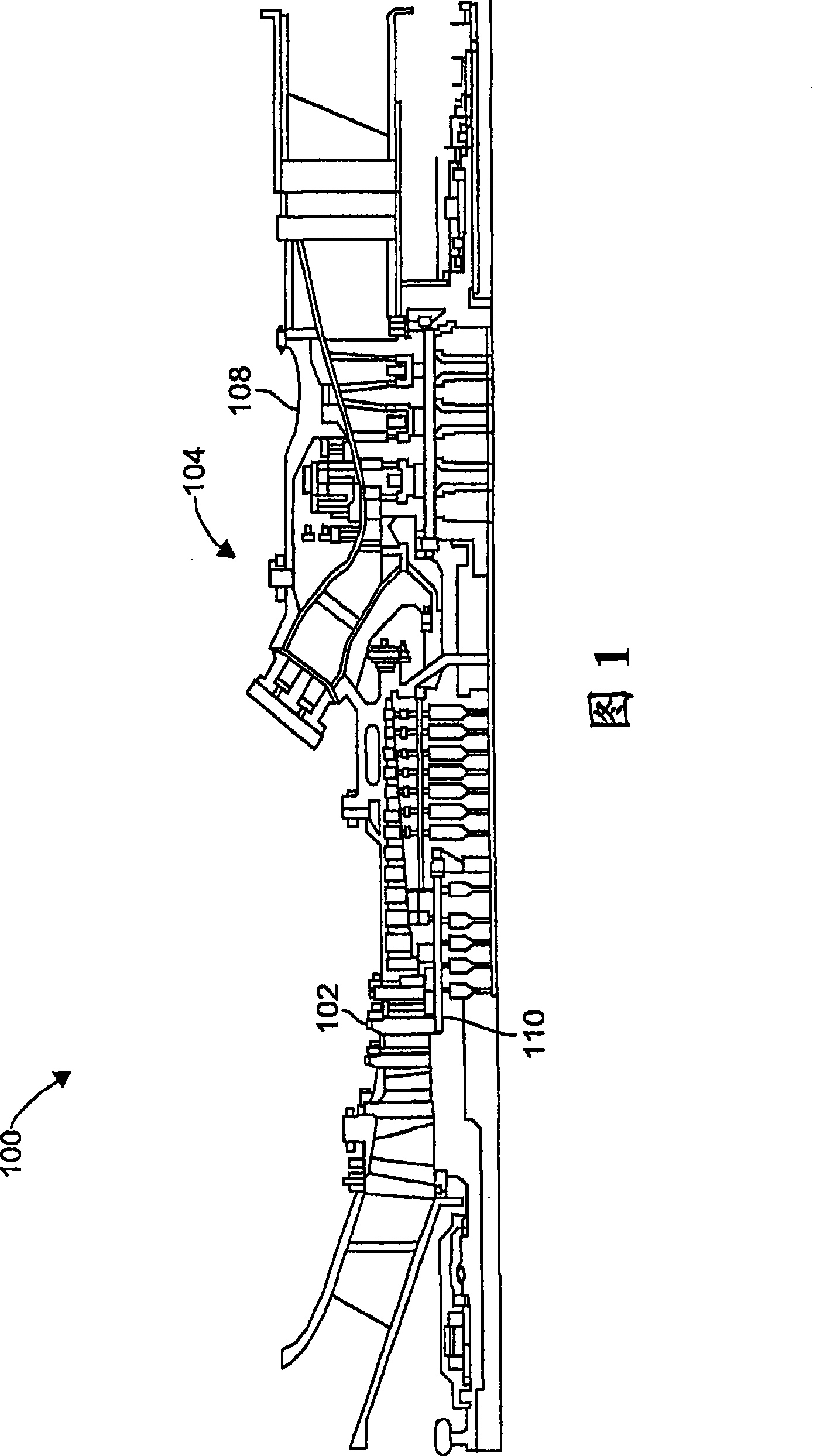
[0018] FIG. 1 is a schematic diagram of an exemplary gas turbine engine 100 . Engine 100 includes a c...


PUM


Abstract

The present invention relates to a method for operating gas turbine engine and a system thereof. More particularly, the invention provides a fuel conveying system (200) which is used for the gas turbine engine (10). The fuel conveying system comprises a plurality of combustors (104) which are grouped to a plurality of combustor groups (20) and a fuel branch pipe that is related with each group ofthe plurality of combustor groups. The fuel conveying system (500) also comprises a control system (500) which can be connected to each fuel branch pipe with an operatable mode. The control system isconfigured for controlling the fuel flowing through each fuel branch pipe to make that a combustor related with a first fuel branch pipe (220) keeps at least one flame selected from diffusion flame and piloted premixed partial diffusion flame. The combustor related with a second fuel branch pipe (222) keeps a premixed flame.

Description

technical field [0001] The present invention relates generally to gas turbine engines and, more particularly, to methods and systems for operating gas turbine engines at significantly lower load conditions with stable combustion and lower emissions. Background technique [0002] A gas turbine engine typically includes a compressor, one or more combustors each having a fuel injection system, and a turbine section. In an engine having multiple combustors, the combustors are typically arranged in an annular array around the periphery of the engine, and most of the combustors are typically interconnected for ignition. The compressor boosts the pressure of the intake air, which then directs the air to the burner, where it is used to cool the walls of the combustion chamber and provide air for the combustion process. In the combustion chamber, compressed air is mixed with fuel, and the mixture is ignited by an ignition source to produce high temperature combustion gases. [0003...

Claims


Application Information

Patent Timeline
IPC IPC(8): F23R3/28
CPCF02C7/228
Inventor G·D·迈尔斯D·A·斯尼德E·莫特D·R·泰格尔J·哈珀S·R·沃奇J·奇特诺
Owner GENERAL ELECTRIC CO
Why Eureka
Try Eureka