Gas turbine combustor having multiple independently operable burners and staging method thereof

a gas turbine and burner technology, applied in the ignition of the turbine/propulsion engine, the fluid coupling, lighting and heating apparatus, etc., can solve the problems of limited pilot fuel ratio, large amount of unburned fuel, so as to improve the fuel staging method, enhance the characteristics of exhaust gas, and achieve combustion stably

Active Publication Date: 2010-09-21
MITSUBISHI POWER LTD
View PDF31 Cites 8 Cited by
  • Summary
  • Abstract
  • Description
  • Claims
  • Application Information

AI Technical Summary

Benefits of technology

[0012]It is an object of the present invention to provide a combustor of a gas turbine which can reduce the unburned portion of a fuel at the time of partial load so as to enhance the characteristics of exhaust gas and can achieve combustion stably, by improving the staging method of the fuel.

Problems solved by technology

However, because the conventional combustor of a gas turbine as described hereinabove applies lean pre-mixed combustion due to reduction of NOx, the fuel is relatively diluted in order to achieve low combustion temperature at the time of partial load, resulting in generation of a large amount of unburned portion of the fuel.
Reduction of the unburned portion of the fuel at the time of partial load is an important issue for the market needs.
However, the upper limit of the pilot fuel ratio is limited by the fuel pressure, and also the upper limit of the ratio of fuel versus air is limited in the combustion area due to the size of the bypass valve.
Moreover, because in the existing operational mode, fuel is supplied to all the main nozzles (eight nozzles in the above-mentioned example of a conventional combustor) and the pilot nozzle (one nozzle) since start-up, naturally, reduction of the unburned portions comes to be limited if nothing is done.
Additionally, the conventional control method of combustion has a tendency to deteriorate the property of exhaust gas and generate combustion vibration and further, an increase in metal temperature of the combustor when the load is low, which needs to be improved.

Method used


Image

  • Gas turbine combustor having multiple independently operable burners and staging method thereof
  • Gas turbine combustor having multiple independently operable burners and staging method thereof
  • Gas turbine combustor having multiple independently operable burners and staging method thereof

Examples


first embodiment

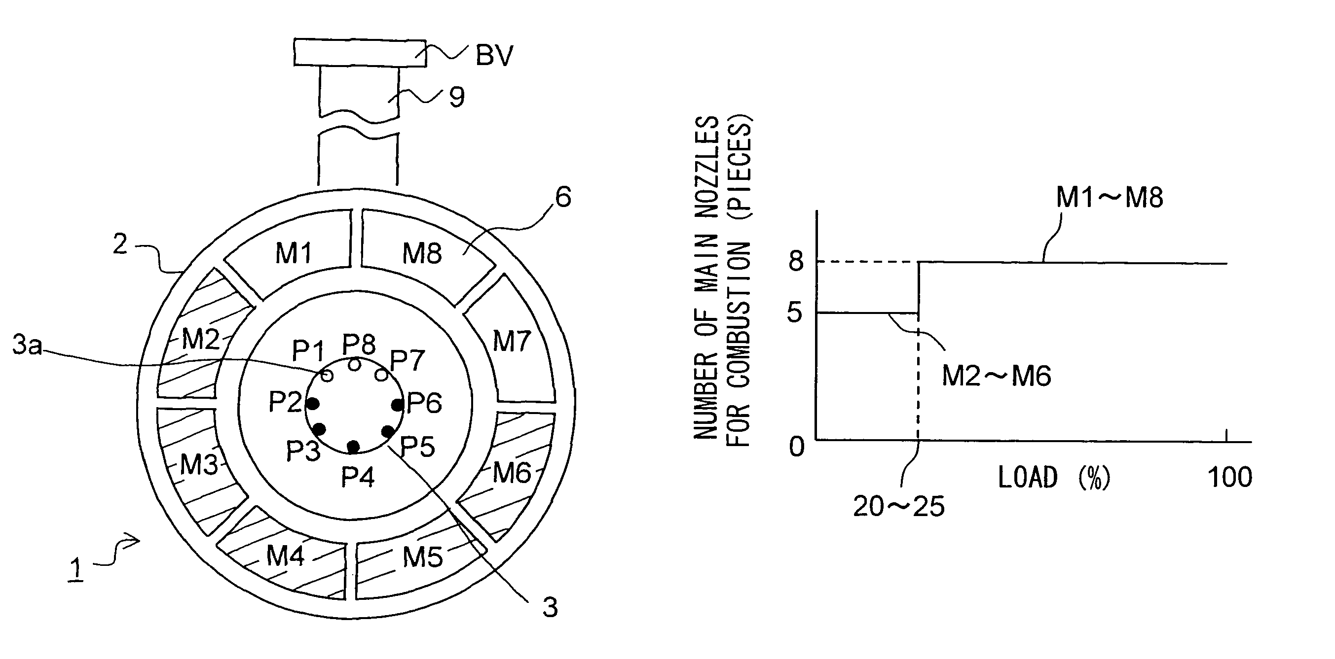
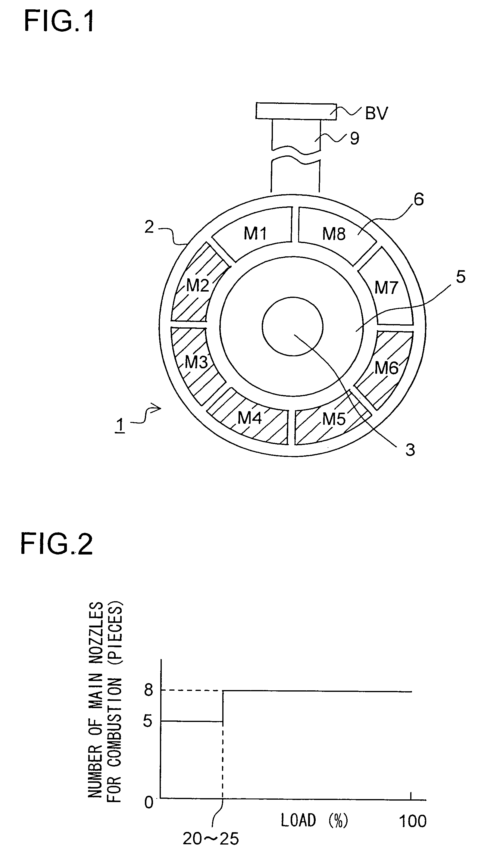
[0038]FIG. 1 is a schematic view showing a combustor of a gas turbine viewed from downstream side in accordance with a first embodiment of the present invention. Same as the example of a conventional combustor of a gas turbine shown in FIG. 18A and FIG. 18B, FIG. 1 illustrates a combustor having eight main nozzles and one pilot nozzle. This is the same with each of the following embodiments. In FIG. 1, the main nozzles 4 being connected to each of main burners 6 (not illustrated herein) are supplied with symbols from M1 through M8 sequentially counterclockwise, starting with the main nozzle on the side of the bypass elbow 9; wherein, for example, combustion is performed in the low load zone only by five main nozzles M2 through M6 being shown with slanting lines and located apart from a bypass elbow 9, and in the partial load zone, combustion is changed over so as to be performed by all the eight main nozzles M1 through M8 by adding the remaining three main nozzles. However, the amou...

second embodiment

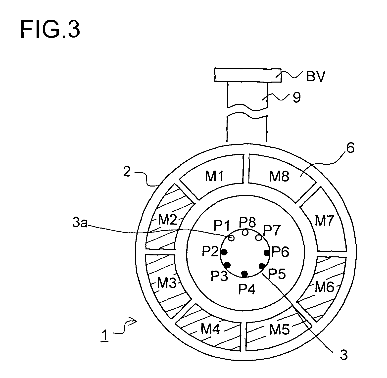
[0044]FIG. 3 is a schematic view showing a combustor of a gas turbine viewed from downstream side in accordance with the second embodiment of the present invention. In this embodiment, in addition to the construction of the above first embodiment, a plurality of pilot holes 3a (eight holes in FIG. 3) being provided to the circumference of the tip of the pilot nozzle 3 implement the staging of the fuel in accordance with the behavior of the main nozzles 4.

[0045]As shown in FIG. 3, the pilot holes 3a are opened so as to be located between each of the main nozzles, being viewed from the central axis. Then, to each of the pilot holes 3a, symbols P1 through P8 are provided counterclockwise sequentially, starting with the pilot hole 3a being positioned between the main nozzles M1 and M2. Wherein, when combustion is performed in the low load zone, for example, by the five main nozzles M2 through M6 shown with slanting lines, the fuel is injected only from the corresponding five holes (show...

third embodiment

[0049]FIG. 5A and FIG. 5B are schematic views showing a combustor of a gas turbine viewed from downstream side in accordance with the third embodiment of the present invention. For the construction of the above first embodiment, a combustor in accordance with the third embodiment is constructed in a manner that the main nozzles performing combustion in the low load zone are distributed to some extent. For example, as shown in FIG. 5A with slanting lines, in the low load zone, combustion may be performed by the main nozzles M2 through M4, M6 and M7 but may not be performed by the main nozzle M5 therebetween. Or, as shown in FIG. 5B with slanting lines, in the low load zone, combustion may be performed by the main nozzles M2, M3 and M5 through M7 but may not be performed by the main nozzle M4 therebetween. In addition, because the main nozzles M1 and M8 are on the side of the bypass elbow 9, in order to prevent inclusion of combustion gas, combustion will not be performed in the low l...


PUM


Abstract

In a combustor of a gas turbine which has a pilot nozzle being installed to the center of the axis of a combustor basket and a plurality of main nozzles being installed to the vicinity of the pilot nozzle and provided with a premixing tool on the outer circumference thereof, wherein, fuel being injected as air-fuel pre-mixture from the main nozzle into the interior of a transition piece forming a combustion chamber downstream of the combustor basket is ignited by diffusion flame being generated by the pilot nozzle in the transition piece so as to generate a premixed flame in the transition piece, wherein combustion is performed by a part of the plurality of main nozzles from start-up until a predetermined load rate and then performed by adding the remaining portion of the plurality of main nozzles when the predetermined load rate is exceeded.

Description

[0001]The present patent application is based on the Patent Application applied as 2004-332884 in Japan on Nov. 17, 2004 and includes the complete contents thereof for reference.BACKGROUND OF THE INVENTION[0002]1. Field of the Invention[0003]The present invention relates to a combustor of a gas turbine and especially relates to a combustor of a gas turbine which is characterized by a staging method of fuel.[0004]2. Description of the Prior Art[0005]The outline of a conventional combustor of a gas turbine will be described hereinafter. FIG. 18A and FIG. 18B are schematic block diagrams showing the construction of a conventional combustor of a gas turbine; and FIG. 18A is a longitudinal cross-sectional view thereof and FIG. 18B is a figure viewed from the downstream side. As shown in FIG. 18A and FIG. 18B, a combustor of a gas turbine comprises a transition piece 10 being provided with an inner space as a combustion chamber and a combustor basket 2 being provided with a mechanism for ...

Claims


Application Information

Patent Timeline
Patent Type & Authority Patents(United States)
IPC IPC(8): F02C1/00F02G3/00
CPCF23R3/343F23R3/286F23R3/28F23R3/38
Inventor SAITOH, TOSHIHIKOOHTA, MASATAKAAKAMATSU, SHINJINOSE, MASAKAZU
Owner MITSUBISHI POWER LTD
Why Eureka
Try Eureka