
Cable clip rotary type anti-bouncing spacer

A rotary, anti-galling technology, which is applied in the direction of the device for maintaining the distance between parallel conductors and the suspension device of the cable, etc., can solve the problems of inability to reduce the torque effect of the conductor, and cannot change the shape of the ice or snow, so as to reduce galloping The effect of reducing the amplitude, reducing tension fluctuations, and improving safety

Inactive Publication Date: 2009-05-06
上海勤功线路器材有限公司
View PDF0 Cites 12 Cited by
  • Summary
  • Abstract
  • Description
  • Claims
  • Application Information

AI Technical Summary

Problems solved by technology

However, due to the fixed clamps used by these spacers, it is impossible to change the shape of icing or snow accumulation on the conductors, and it is impossible to reduce the resistance (horizontal force relative to the ground) and lift (vertical force) of the conductors. ) and torsional force, etc., so the above problems cannot be solved

Method used

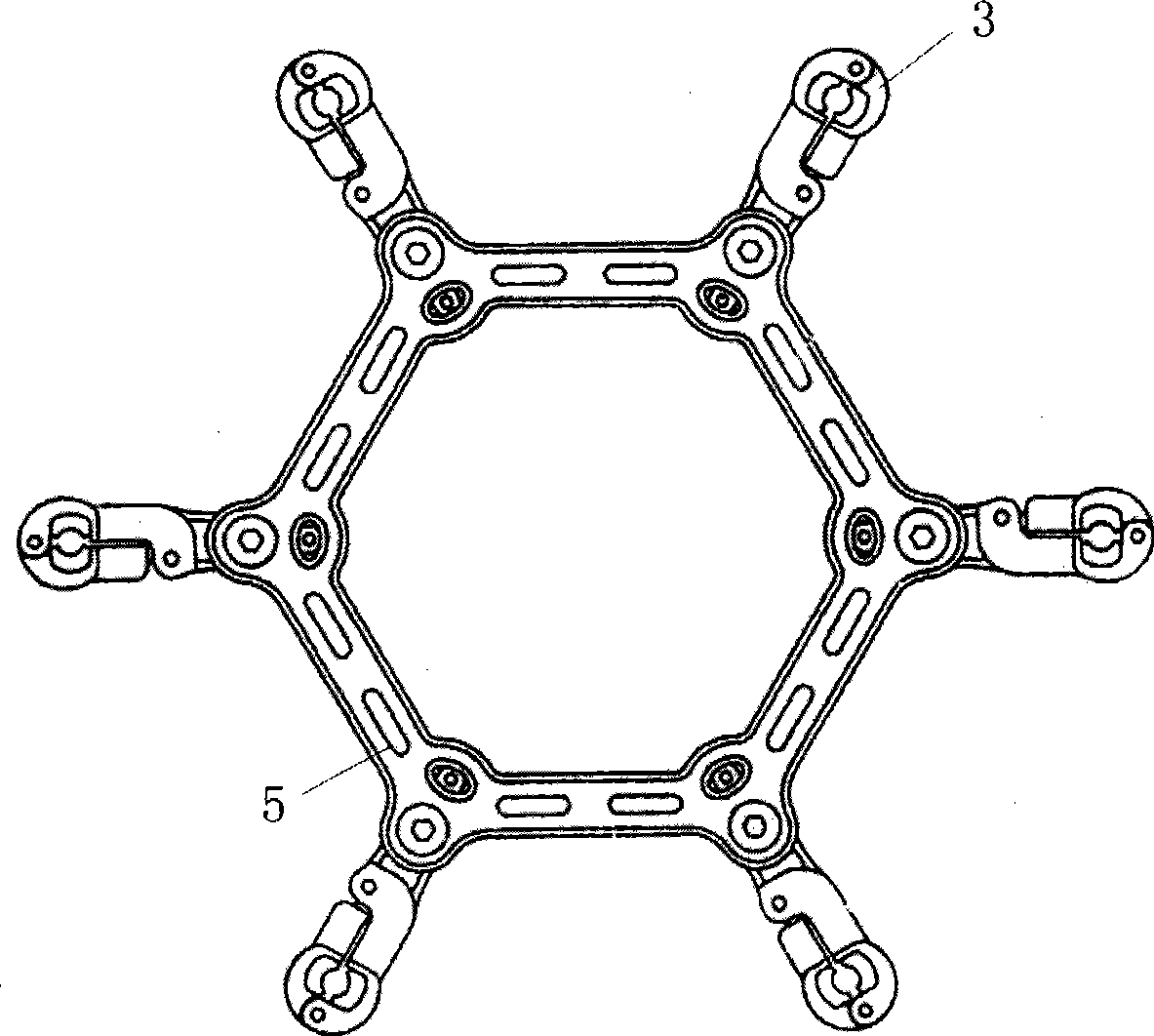
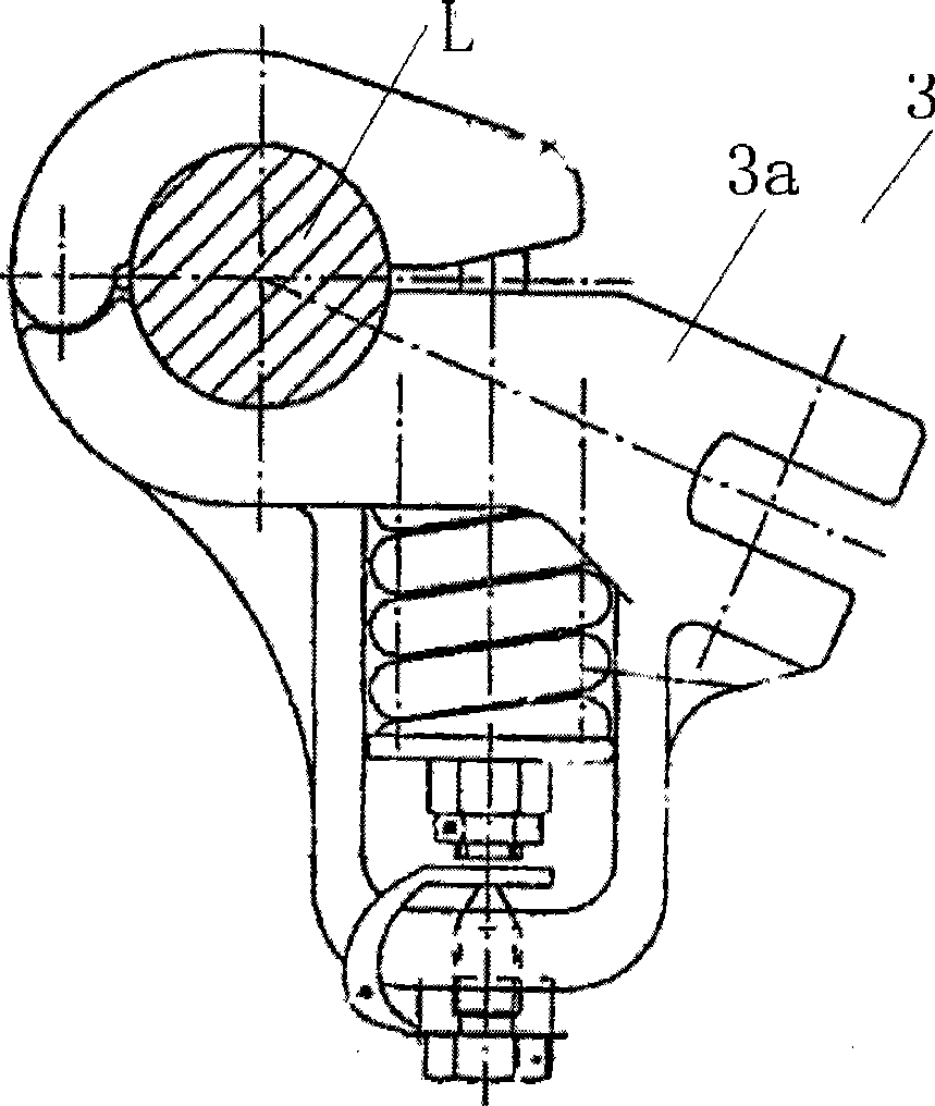

Image

  • Cable clip rotary type anti-bouncing spacer
  • Cable clip rotary type anti-bouncing spacer
  • Cable clip rotary type anti-bouncing spacer

Examples


Embodiment 1

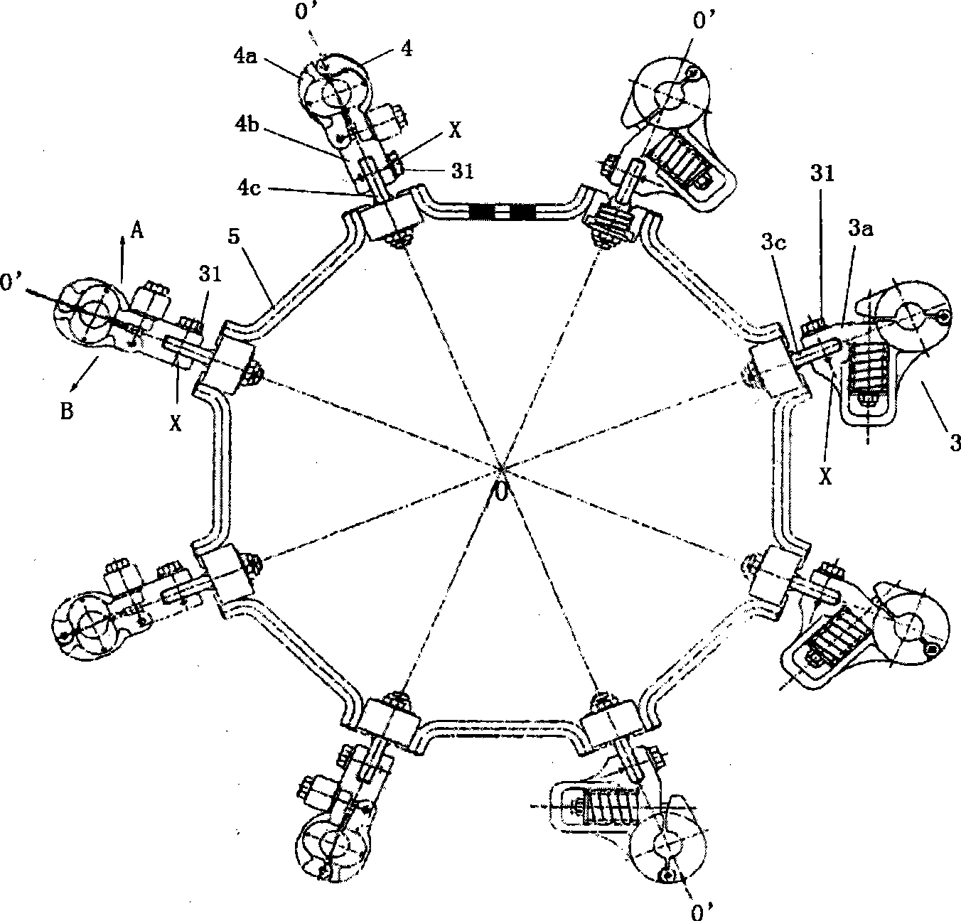
[0036] figure 2 It is a front view of the eight-split wire protection spacer 1 with four fixed clamps 3 and four rotary clamps 4 of the present invention. In this figure, four fixed wire clamps 3 and four rotary wire clamps 4 are continuously installed on one side of the wire clamp bracket 5 .

[0037] exist figure 2 Among them, the spacer bar 1 of the present invention has eight wire clips and a regular polygon (corresponding to the number of wire clips, octagonal in this embodiment) wire clip bracket 5, and the wire clips are installed at equal intervals. on bracket 5. The wire clamps include a fixed type wire clamp 3 and a rotary type wire clamp 4 .

[0038] In this example, if figure 2 As shown, the quantity of the fixed line clamps 3 is equal to the quantity of the rotary line clamps 4, each accounting for half of the entire line clamps.

[0039] As shown in the figure, the rotary clamp 4 mainly includes a clamp head 4a, a clamp slider 4b and a support rod 4c. Th...

Embodiment 2

[0057] In Embodiment 1, except that 6 wire clips are installed on the wire clip rotary anti-flapping spacer, in which there are three fixed wire clips 3 and three rotary wire clips 4, the others are the same as in Embodiment 1, The clamp rotary anti-galling spacer of the present invention is obtained.

Embodiment 3

[0059] In embodiment 1, except that four wire clips are installed on the wire clip rotary anti-flapping spacer, in which there are two fixed wire clips 3 and two rotary wire clips 4, the others are the same as embodiment 1, The clamp rotary anti-galling spacer of the present invention is obtained.


PUM


Abstract

The invention relates to a wire clamp rotary anti-galloping spacer bar which comprises a plurality of wire clamps (3a, 4a) and a polygonal wire clamp support (5). The wire clamps used for wire protection comprises fixed wire clamps (3a) and rotary wire clamps (4a), wherein the rotary wire clamps can be rotated or swung perpendicularly to the direction of lengths of the wires. The fixed wire clamps and the rotary wire clamps are symmetrically arranged or arranged at intervals. The spacer bar can prevent the constant wing-shaped icing or snow deposit from forming on the wires at any moment, reduce the resistance, the elevating force and the moment of the torque force of the wires under the state of the windward side covered with ice and snow and under the state of the galloping wires, reduce the excessively large tension change of the wires, as well as the galloping amplitude and the overturn of the wires, therefore, the galloping trail of the wires is changed into a non circular trail, and the wires are prevented or eased from being broken or falling off due to accumulation of fatigue; the mechanical damage of the wire galloping phenomenon to the transmission equipment is avoided or reduced, and the ice and snow resistance and the security of the overhead transmission line are enhanced.

Description

technical field [0001] The invention relates to a protective fitting for overhead high-voltage split wires, in particular, the invention relates to a clamp-rotating anti-galling spacer for separately clamping and supporting a plurality of overhead high-voltage transmission lines. Background technique [0002] A high-voltage overhead transmission line generally has multiple high-voltage conductors, such as four, six or eight high-voltage conductors. Overhead transmission lines often dance under the action of wind, which causes excessive tension changes on the conductor itself, causing the conductor to break and drop due to fatigue accumulation. In severe cases, this galloping phenomenon will cause mechanical damage to equipment such as iron tower components, insulator strings, etc., and even worse, cause the iron tower to collapse. Obviously, the greater the range of dancing, the easier it is to cause the above problems. [0003] For this reason, people in the field have us...

Claims


Application Information

Patent Timeline
Patent Type & Authority Applications(China)
IPC IPC(8): H02G7/12H02G7/08
Inventor 周中明袁骏洪芳华房岭锋张锦秀张永隆张刚强顾撼宇金成生贲飞俞来意姚炜峻陈文隆
Owner 上海勤功线路器材有限公司
Learn More