Ventilated transformer enclosure

A technology for transformers and casings, which is applied in the field of air-cooled transformer casings, and can solve problems such as fires and damage to electrical devices

Inactive Publication Date: 2009-05-06
ABB TECH AG
View PDF0 Cites 7 Cited by
  • Summary
  • Abstract
  • Description
  • Claims
  • Application Information

AI Technical Summary

Problems solved by technology

[0003] Transformer enclosures often accumulate heat generated by the transformer, which can raise the temperature inside the enclosure to undesired levels and cause damage to electrical installations, or worse, fire

Method used


Image

  • Ventilated transformer enclosure
  • Ventilated transformer enclosure
  • Ventilated transformer enclosure

Examples


Embodiment Construction

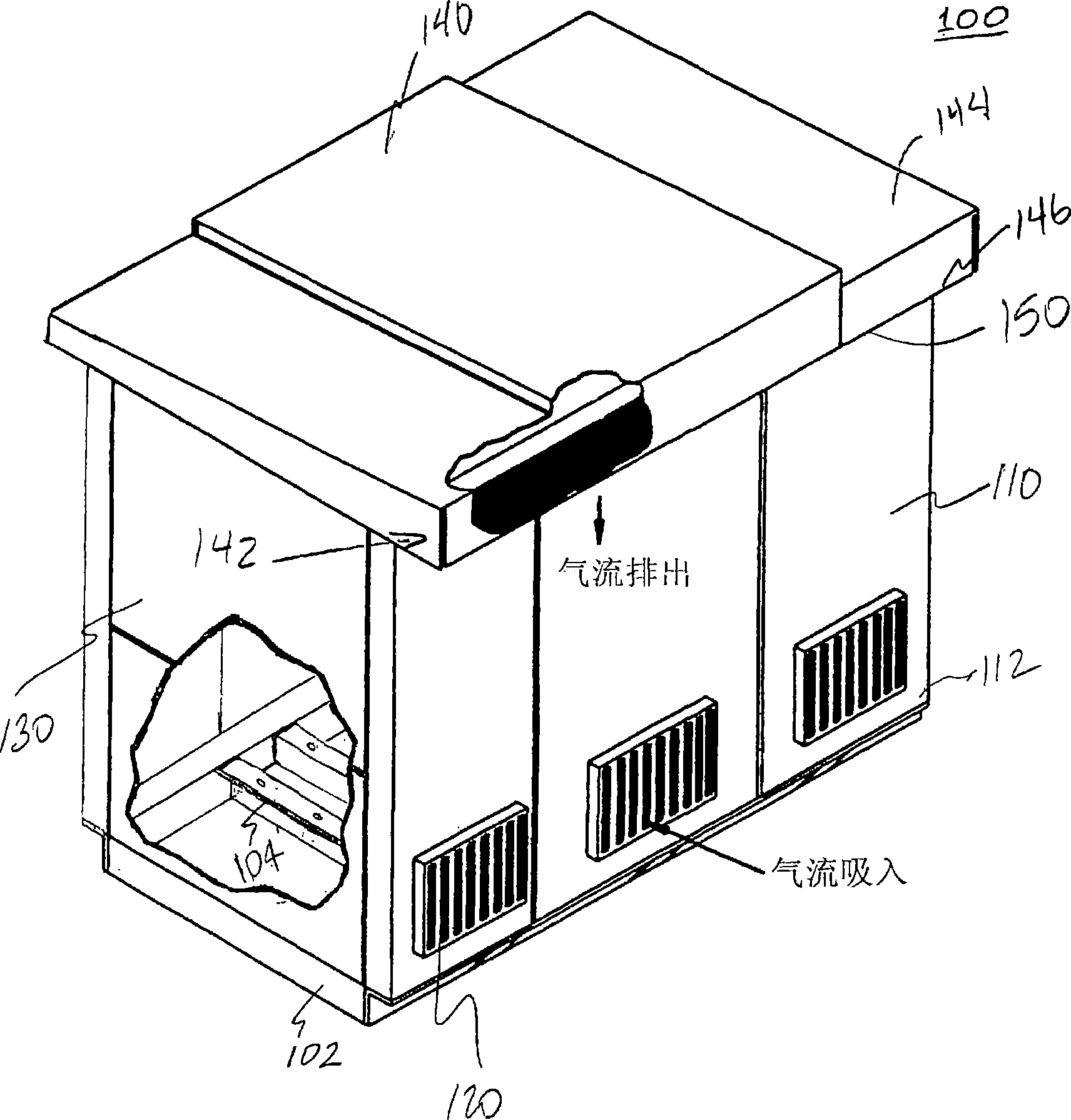
[0014] A transformer enclosure according to one embodiment comprises means for enclosing a volume. figure 1 One embodiment of a transformer housing 100 according to one embodiment of the present invention is shown. The transformer enclosure 100 includes a base structure 102 . The base structure 102 may include means, such as brackets 104, to support a transformer (not shown) within the enclosure. One or more walls 110 are secured to the base structure 102 , typically at a base 112 of the walls 110 . Here, the bottom 112 of the wall 110 may be any part near the bottom of the wall, not necessarily at the bottom edge. The wall 110 is preferably substantially perpendicular to the base structure 102, for example at an angle of substantially 90°, for example between 80°-100°. It is understood that in other embodiments, the angle formed by the wall 110 and the base structure 102 is substantially different from 90°, such as 30°, 45°, 60°, 120°, 135°, 150°, and any difference thereb...


PUM


Abstract

A transformer enclosure includes a base structure, a wall secured to the base structure, and an airflow aperture located in a lower portion of the wall. A roof structure is secured to the wall and has an overhang portion extending beyond the wall outward from the enclosure. The overhang portion has a roof top panel and a roof bottom panel. The roof bottom panel has a roof airflow aperture. The transformer enclosure can include means for enclosing a volume and airflow means for cooling a transformer within the enclosed volume, where the airflow means includes a plurality of opposing channels.

Description

technical field [0001] The present invention generally relates to transformer housings. More specifically, the present invention relates to air-cooled transformer enclosures. Background technique [0002] Transformers and other electrical equipment are usually housed in enclosures. Enclosures are used for various reasons such as providing mechanical protection to transformers as a safety measure against human or animal exposure to electrical current, providing ease of installation and internal wiring for several electrical installations, and protecting electrical installations from environmental influences such as rain , snow, temperature, etc. [0003] Transformer enclosures often accumulate heat generated by the transformer, which can raise the temperature inside the enclosure to undesired levels and cause damage to electrical installations, or worse, fires. To compensate, the enclosure may include some form of air cooling to exhaust hot air in the enclosure and replace...

Claims


Application Information

Patent Timeline
Patent Type & Authority Applications(China)
IPC IPC(8): E04H1/00E04H5/04
CPCH01F27/085H05K7/20136H01F27/025H02B7/06E04H5/04
Inventor 查利·H·萨弗拉什·B·霍顿盖伊·D·拉姆齐乔伊·钱德勒
Owner ABB TECH AG
Why Eureka
Try Eureka