Continuous washing device washing groove for band

A technology for cleaning equipment and cleaning tanks, which is applied to lighting and heating equipment, cleaning methods and utensils, and cleaning methods using liquids. Expansion, good anti-washing liquid diarrhea effect, good isolation effect

Active Publication Date: 2009-05-13
四川中科百博太阳能科技有限公司
View PDF0 Cites 17 Cited by
  • Summary
  • Abstract
  • Description
  • Claims
  • Application Information

AI Technical Summary

Problems solved by technology

[0003] The purpose of the present invention is to overcome the problem that the cleaning liquid in the cleaning tank in the prior art is easily splashed outside the tank body and the cleaning liquid interferes with each other in the cleaning tank body, and to provide a cleaning tank with anti-sputtering effect and adopts Multi-chamber continuous strip cleaning equipment cleaning tank that overcomes the mutual interference of cleaning fluids between various cleaning tanks

Method used


Image

  • Continuous washing device washing groove for band
  • Continuous washing device washing groove for band
  • Continuous washing device washing groove for band

Examples


Embodiment

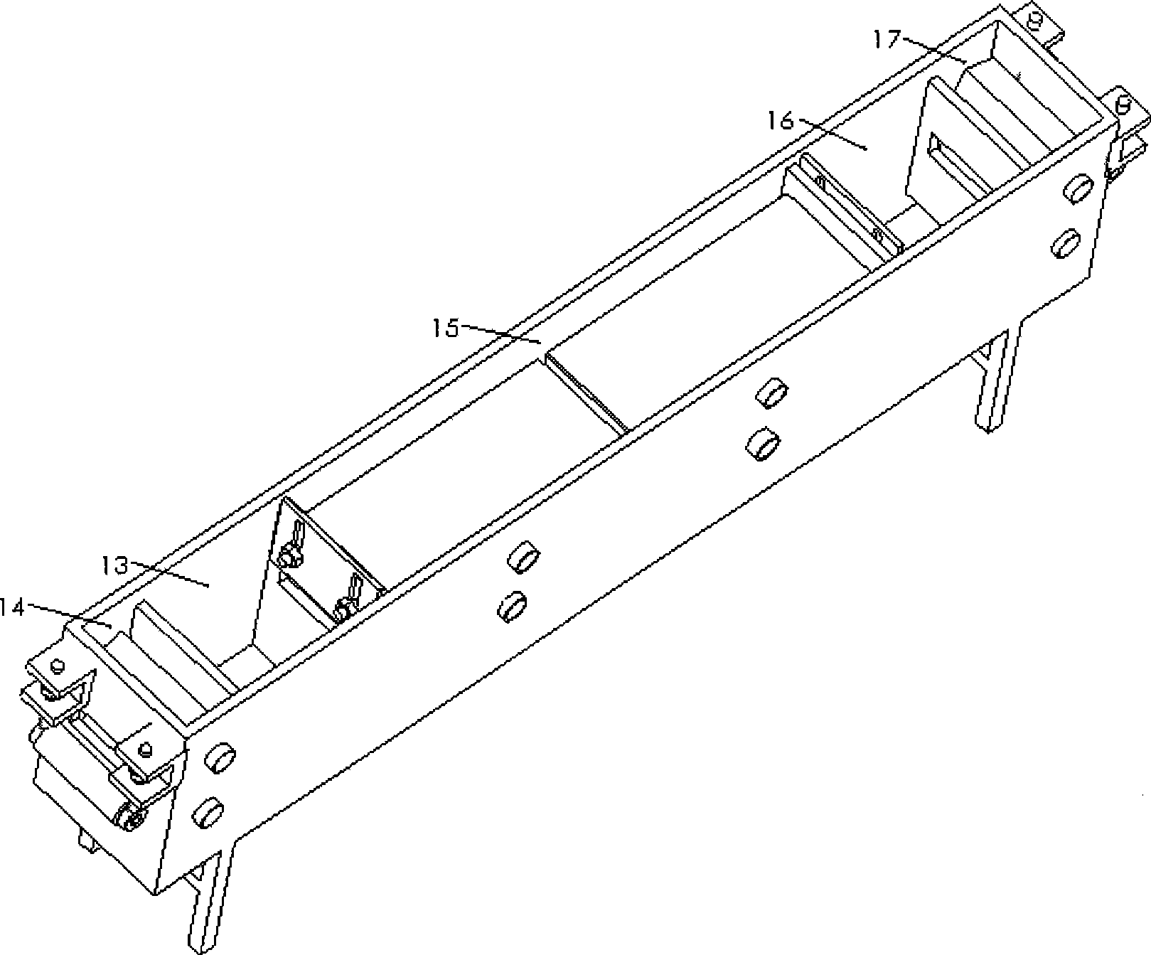
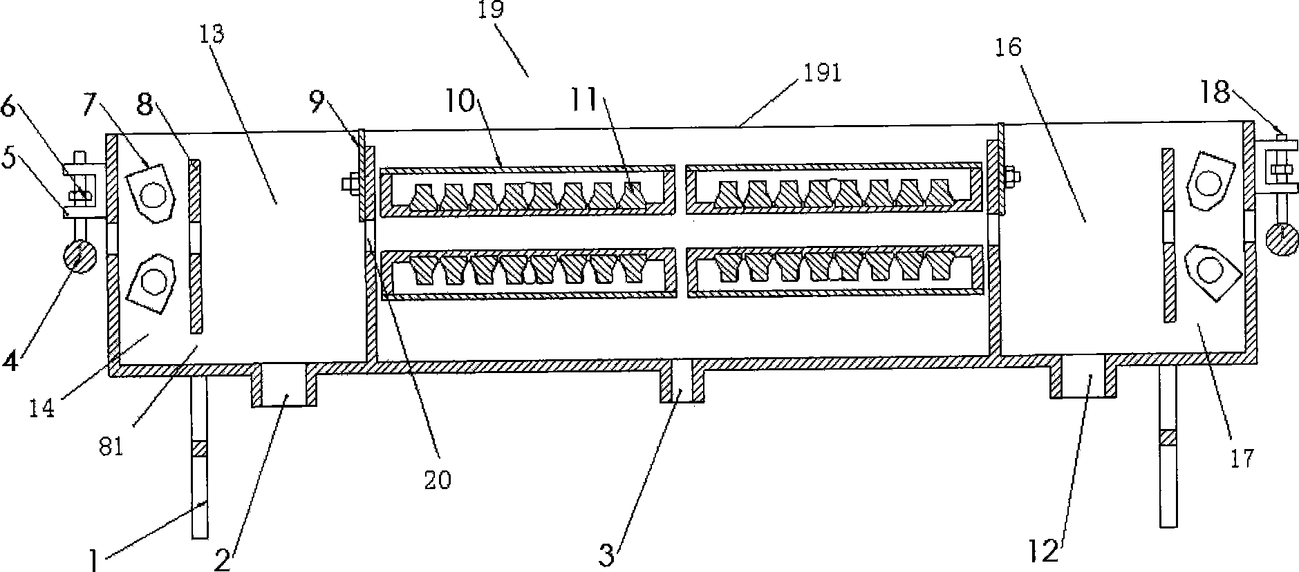
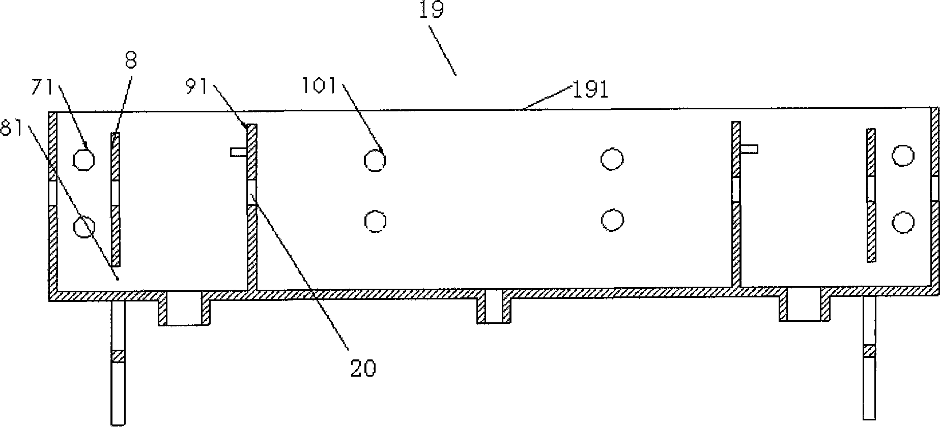
[0025] see figure 1 , figure 2 with Figure 4 As shown, a cleaning tank of continuous strip cleaning equipment consists of five chambers, including two wind shear chambers, two isolation chambers and a main cleaning chamber. The specific composition is as follows:

[0026] Including a frame 1 and a tank body 19 located on the frame 1; on the tank body 19, a right isolation chamber 13 and a left isolation chamber 16 for loading cleaning liquid to clean the strip are symmetrically arranged. Between the right isolation chamber 13 and the left isolation chamber 16, a main cleaning chamber 15 for ultrasonically cleaning the upper and lower surfaces of the strip is provided, and in the right isolation chamber 13 and the left isolation chamber 16, a main cleaning chamber 15 for conveying the strip is provided. The first water outlet 2 and the second water outlet 12 are respectively provided on the strip through hole 20 and the base plate, and the water inlet 3 is provided on the m...


PUM


Abstract

The invention discloses a cleaning trough for strip continuous cleaning equipment. The cleaning trough comprises a frame and a trough body arranged on the frame, wherein, a right isolation chamber and a left isolation chamber which are equipped with washing liquid for cleaning strips are arranged on the trough body in a bilateral symmetry manner; a main cleaning chamber used for conducting the ultrasonic cleaning on the upper and the lower surfaces of strips is arranged between the right isolation chamber and the left isolation chamber; strip passing holes for delivering strips are formed in the right isolation chamber and the left isolation chamber; a first water outlet and a second water outlet hole are respectively formed on each of bottom boards of the right isolation chamber and the left isolation chamber; and a water inlet is formed on a bottom board of the main cleaning chamber. The invention adopts the design of a multi-chamber structure to have good isolation function, reduce the mutual interference between the trough bodies, facilitate multi-trough type cleaning, and better utilize the strip cleaning equipment system; and the corrosion to the external parts, which is caused by the washing liquid leakage, is eliminated.

Description

technical field [0001] The invention relates to a cleaning container of a continuous strip cleaning equipment system, in particular to a component part of a strip cleaning equipment system. Background technique [0002] At present, most of the cleaning tanks of continuous strip cleaning equipment are only double chambers. During the working process, the cleaning liquid is easily splashed outside the tank body, and when multiple tanks are used for cleaning, the cleaning liquid between the tanks is likely to interfere, causing The concentration of the cleaning solution decreases rapidly, so that the cleaning effect of the strip is not good. Contents of the invention [0003] The purpose of the present invention is to overcome the problem that the cleaning liquid in the cleaning tank in the prior art is easily splashed outside the tank body and the cleaning liquid interferes with each other in the cleaning tank body, and to provide a cleaning tank with anti-sputtering effect ...

Claims


Application Information

Patent Timeline
Patent Type & Authority Applications(China)
IPC IPC(8): B08B3/12B08B3/04F26B5/00
Inventor 徐刚黄华凛陈丽华苗蕾黄春明
Owner 四川中科百博太阳能科技有限公司
Why Eureka
Try Eureka