Mould with waste material slide-out component

A scrap and component technology, applied in the field of molds with scrap slip-out parts, can solve problems such as mold design limitations, scrap removal difficulties, and production line stoppages

Inactive Publication Date: 2010-07-28
FUJI RAYHOO TECH WUHU
View PDF0 Cites 1 Cited by
  • Summary
  • Abstract
  • Description
  • Claims
  • Application Information

AI Technical Summary

Problems solved by technology

[0002] An existing mold with a waste material slide-out part is usually used in a non-manually operated stamping line such as a high-speed line and a multi-station. The angle of the waste chute is more than 25 degrees, which requires a larger height of the mold space. When the height of the mold space is small, it will lead to difficulties in removing waste or poor sliding, instead of manual operation of the punching line. The smoothness of the waste material sliding is strictly required, and the waste material is not allowed to be difficult to slide or the material is not smooth. Since there is no manual auxiliary discharge of the waste material, once the waste material is accumulated due to poor sliding, it will cause the production line to stop. Therefore, the design of the mold is limited

Method used


Image

  • Mould with waste material slide-out component
  • Mould with waste material slide-out component
  • Mould with waste material slide-out component

Examples


Embodiment Construction

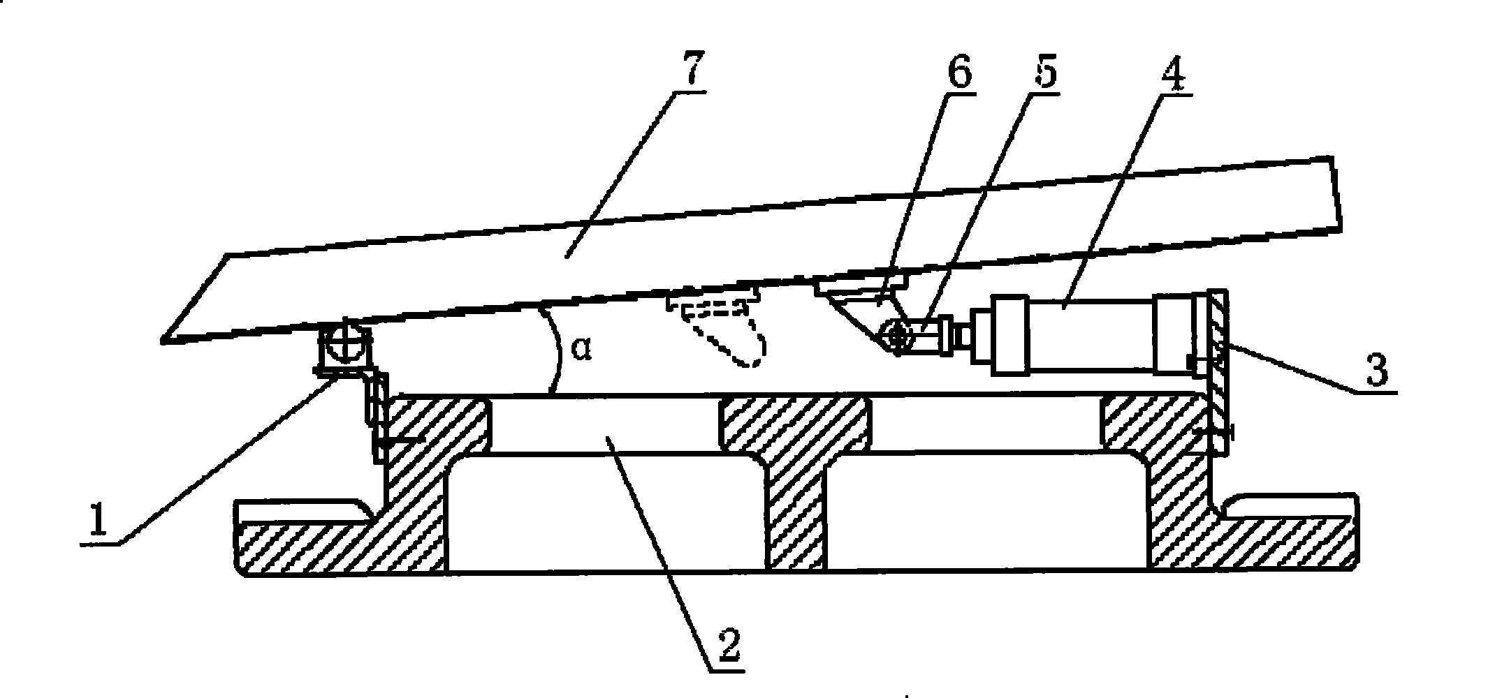
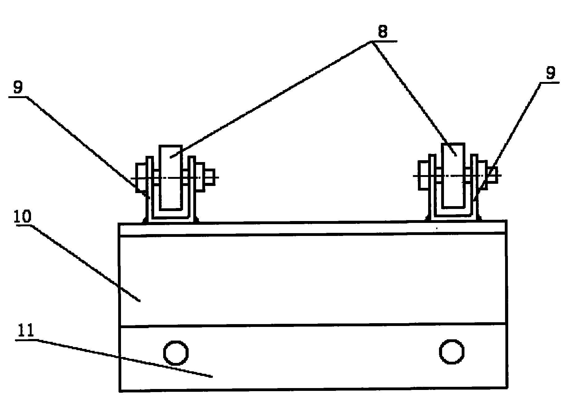
[0015] by figure 1 , figure 2 , image 3 As shown, a mold with a waste sliding part includes a waste chute 7, a rotating wheel mechanism 1, a pneumatic reciprocating mechanism, the waste chute 7 is arranged obliquely above the lower mold body 2, and the rotating wheel mechanism 1 is fixed to the lower mold On one side of the body 2, the rotating wheel mechanism 1 includes a connecting plate 11, a supporting angle frame 10, a wheel frame 9 and a rubber wheel 8. The connecting plate 11 is fixed on the lower mold body 2 by screws, and the wheel frame 9 is welded to the supporting angle frame 10 Above, the supporting angle bracket 10 and the connecting plate 11 are firmly welded. One end of the waste chute 7 is placed on the rubber wheel 8, and the distance between the two rubber wheels 8 can be adjusted, depending on the width of the waste chute, to ensure that the waste chute is stable when it moves. The pneumatic reciprocating mechanism includes a support plate 3 connected wit...


PUM


Abstract

The invention discloses a die with a scrap sliding-out component, which comprises a scrap sliding chute (7) inclinedly arranged above a lower die (2). A rotating wheel mechanism (1) is arranged on and fixedly connected with one side of the lower die (2), a driving reciprocating mechanism spaced with the rotating wheel mechanism (1) is also arranged on the lower die (2), a rotary lug (6) is arranged at the end part of driving reciprocating mechanism and is fixedly connected with the lower surface of the scrap sliding chute (7), and a rotating wheel of the rotating wheel mechanism (1) is in rolling contact with the lower surface of the scrap sliding chute (7). By using the structure, the die with the scrap sliding-out component can reduce the angle of the scrap sliding chute, thereby widening the though of designing the die with the scrap sliding-out component.

Description

Technical field [0001] The invention relates to molds, and more particularly to a mold with scrap sliding parts. Background technique [0002] Existing molds with scrap sliding parts are usually used in non-manually operated stamping lines such as high-speed lines and multi-stations. In order to ensure the smooth sliding out of trimming waste, it is necessary to ensure that the scraps slide out of the parts during mold design. The angle of the waste chute is more than 25 degrees, which requires a larger height for the mold space. When the height of the mold space is small, it will lead to difficulties in removing waste or poor slippage, instead of manual operation of the stamping line. There are strict requirements for the smoothness of the waste slipping, and it is not allowed to have difficulty sliding or poor slippage of the waste. Since there is no manual waste discharge, once the accumulation of waste due to poor sliding occurs, the production line will stop. Therefore, the...

Claims


Application Information

Patent Timeline
Patent Type & Authority Patents(China)
IPC IPC(8): B21D45/02
Inventor 殷言春夏文军
Owner FUJI RAYHOO TECH WUHU
Why Eureka
Try Eureka