Light combined beam moving trolley

A combined and lightweight technology, applied in bridges, bridge maintenance, bridge reinforcement, etc., can solve problems such as difficult approval of blockade plans, increased manpower and material resources, and increased safety hazards

Active Publication Date: 2016-08-24
CHINA RAILWAY SIXTH GRP CO LTD +1
View PDF5 Cites 0 Cited by
  • Summary
  • Abstract
  • Description
  • Claims
  • Application Information

AI Technical Summary

Problems solved by technology

Due to the large workload of hoisting the plate girder, the blockade time is long. If the existing bridge has multiple spans, the number of blockades will increase accordingly. Not only will the investment in manpower and material resources increase, but also the hidden dangers will increase, and at the same time, it will have a greater impact on railway transportation. , the construction has the problem that the blockade plan is difficult to approve

Method used


Image

  • Light combined beam moving trolley
  • Light combined beam moving trolley
  • Light combined beam moving trolley

Examples


Embodiment Construction

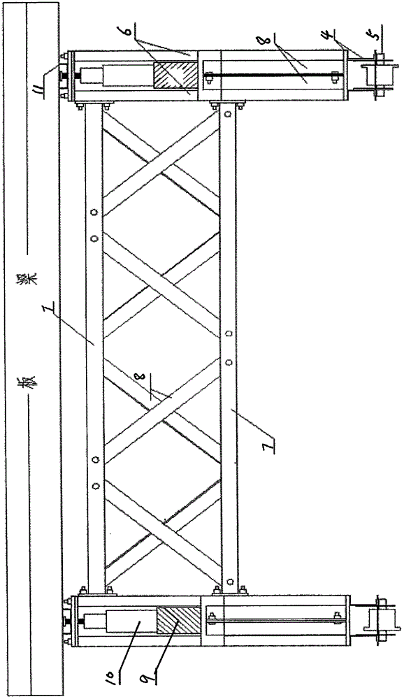
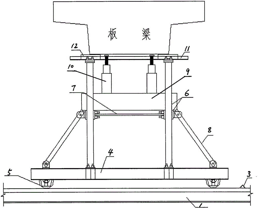
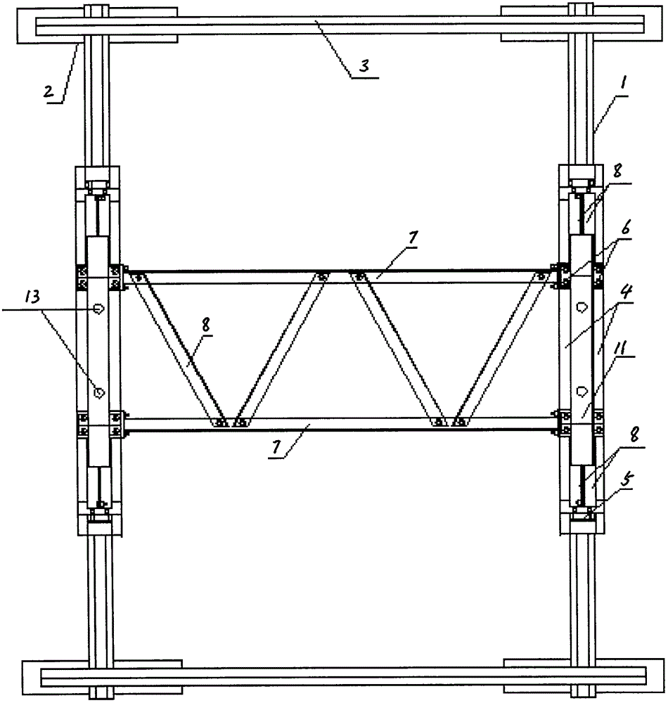
[0012] Such as Figure 1-Figure 3 As shown, at the beam position that needs to be slid out, two tracks 1 are laid along the sliding direction, and short wooden sleepers 2 (spacing 0.5m) are set up under the track 1, and car stops 3 are set at both ends of the track 1 to prevent the car from slipping. Bottom steel frame 4 adorns two pairs of wheels 5 to cooperate with track 1. The supporting steel frame is divided into a vertical supporting steel frame 6, a horizontal supporting steel frame 7 and an oblique supporting steel frame 8. The four symmetrical vertical supporting steel frames 6 are connected with the bottom steel frame 4 through bolts, and the vertical supporting steel frame 6 and the horizontal support steel frame 7 are added with an oblique support steel frame 8 and fixed with bolts, and the upper and lower horizontal support steel frames 7 and the vertical support steel frames 6 are spliced ​​into a load-bearing frame. An oblique support steel frame 8 is added bet...


PUM


Abstract

The invention discloses a light-duty combined beam-moving trolley. The main structure is that two pairs of wheels are installed under the bottom steel frame to cooperate with the track, and four symmetrical vertical steel frames are connected with the bottom steel frame by bolts. An oblique supporting steel frame is added between the steel frame and the horizontal supporting steel frame and fixed with bolts. The upper and lower horizontal supporting steel frames are spliced ​​with the vertical supporting steel frame to form a load-bearing frame. Sleepers are placed on the horizontal supporting steel frame, and jacks are set on the sleepers. , each pair of jacks is fixed to a girder, and the plate girder is lifted and placed on the trolley by four jacks, and the plate girder is removed. The present invention uses channel steel, angle steel and bolts to assemble a load-bearing frame, which can meet the requirements of a maximum load of 10t and a stable structure.

Description

technical field [0001] The invention relates to a trolley, in particular to a light-duty combined beam-moving trolley for sliding out an existing concrete slab girder in the reconstruction of an existing railway bridge. Background technique [0002] At present, the construction of dangerous bridge projects on existing domestic railway lines has been carried out in many places. Among the dangerous bridges, small bridges and culverts account for a considerable proportion, and the structures are mostly stone piers and concrete slab girders. Most of the design and construction schemes are to block the line and hang out the slab girder. Due to the large workload of hoisting the plate girder, the blockade time is long. If the existing bridge has multiple spans, the number of blockades will increase accordingly. Not only will the investment in manpower and material resources increase, but also the hidden dangers will increase, and at the same time, it will have a greater impact on ...

Claims


Application Information

Patent Timeline
Patent Type & Authority Patents(China)
IPC IPC(8): E01D22/00
Inventor 王云峰贾明敏初艳伟吴建英杭一伟张瑜杨希润张玉光
Owner CHINA RAILWAY SIXTH GRP CO LTD
Why Eureka
Try Eureka