Bearing pallet stack structure and bearing pallet

A technology of stacking structure and carrying plate, applied in the field of stacking structure, can solve the problems of extraction and foreign matter particle residue, etc.

Inactive Publication Date: 2013-01-02
AU OPTRONICS CORP
View PDF0 Cites 1 Cited by
  • Summary
  • Abstract
  • Description
  • Claims
  • Application Information

AI Technical Summary

Problems solved by technology

In any two adjacent carriers, since the upper carrier is in close contact with the lower carrier, when the carrier stack structure is placed in a packaging bag for vacuum packaging, the foreign particles in each carrier will Unable to effectively pull away from the carrier tray, resulting in foreign particles remaining in the stack structure of the vacuum-packed carrier tray

Method used


Image

  • Bearing pallet stack structure and bearing pallet
  • Bearing pallet stack structure and bearing pallet
  • Bearing pallet stack structure and bearing pallet

Examples


Embodiment Construction

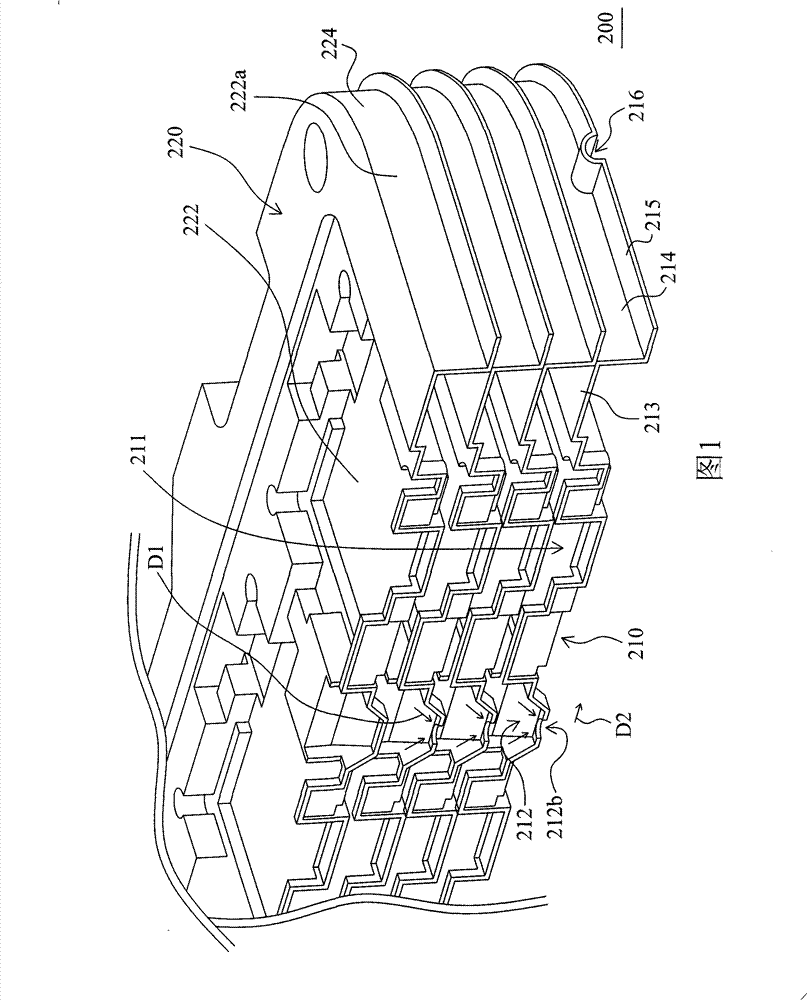
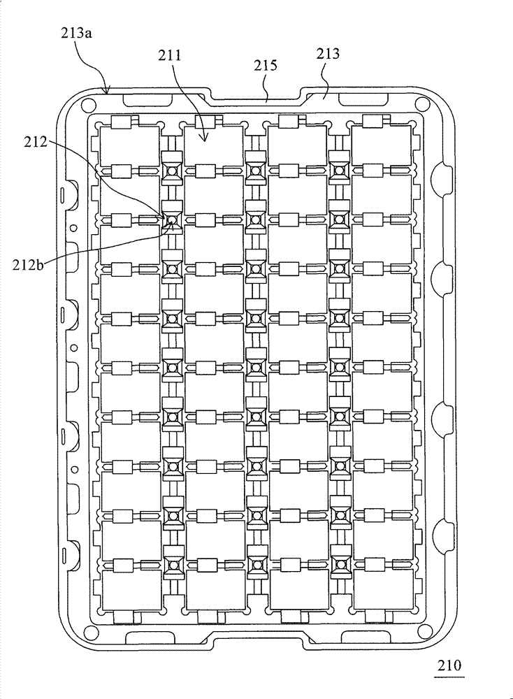
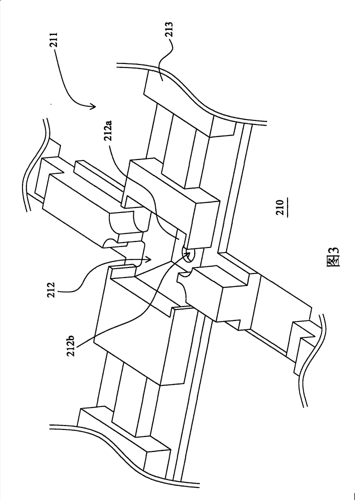
[0034] FIG. 1 shows a perspective cross-sectional schematic view of a stacked structure of carrier discs according to an embodiment of the present invention. figure 2 A schematic top view of the carrier discs of the carrier disc stack structure in FIG. 1 is shown. Figure 3 shows the figure 2 A partially enlarged schematic diagram of the carrier plate. Please refer to Figure 1, figure 2 As shown in FIG. 3 , the susceptor stack structure 200 of this embodiment includes a plurality of susceptors 210 and an upper cover 220 . The carrying plates 210 are stacked on each other, and each carrying plate 210 has a plurality of carrying areas 211 and a plurality of depressions 212 . Each carrier tray 210 includes a carrier body 213 and a first spacer 214 . In each carrier tray 210 , the carrier areas 211 and the recesses 212 are disposed on the carrier body 213 , and each recess 212 is adjacent to at least one of the carrier areas 211 . Each carrying area 211 is for example used to ...


PUM


Abstract

The invention relates to a bearing plate stack structure and a bearing plate. The bearing plate stack structure includes a plurality of bearing plates mutually stacked and an upper cover configured on the top layer of bearing plate. Each bearing plate has a plurality of bearing areas, a plurality of depressions, a bearing body and a first interval part. In each bearing plate, the bearing areas and the depressions are configured with the bearing body and all the depressions are adjacent to at least one bearing areas and are provided with the bottom parts and through holes positioned at the bottom parts. In each bearing plate, the first interval part is configured around a bearing body, and the first interval part and the bottom part of each depression are positioned on the same side of thebearing body. In any two adjacent bearing plates, each through hole of the upper layer is communicated with one of the through hole of the lower layer, and the first interval part of the upper layer is closely connected with the lower bearing body. The upper cover comprises a cover body which covers the top layer of bearing body and a second internal part which is configured around the cover bodyand closely connected with the top layer of bearing body. Therefore, foreign particle residuals can not easily occur on each bearing area of the bearing plate with stack structure and vacuum packaging.

Description

technical field [0001] The present invention relates to a stacking structure, and in particular to a stacking structure of carrier discs. Background technique [0002] The existing tray stacking structure includes a plurality of trays stacked on each other, and each tray is used for carrying a liquid crystal panel respectively. In any two adjacent carriers, since the upper carrier is in close contact with the lower carrier, when the carrier stack structure is placed in a packaging bag for vacuum packaging, the foreign particles in each carrier will Unable to effectively pull away from the carrier plate, resulting in foreign particles remaining in the stack structure of the vacuum-packed carrier plate. Therefore, it is really necessary to improve the existing stacking structure of the carrier discs. Contents of the invention [0003] The object of the present invention is to provide a stacked structure of carrier discs, which is less likely to have foreign particles remai...

Claims


Application Information

Patent Timeline
Patent Type & Authority Patents(China)
IPC IPC(8): B65D21/032B65D85/48B65D19/00B65D81/05B65B31/04
Inventor 陈威儒邓友渊
Owner AU OPTRONICS CORP
Why Eureka
Try Eureka