Instrument cabinet

A casing and instrument technology, applied in the field of instruments, can solve problems such as unreasonable structure of instrument casings, and achieve the effects of increasing use space, increasing heat transfer, and facilitating assembly

Active Publication Date: 2009-05-20
ZHEJIANG SUPCON INSTR
View PDF1 Cites 1 Cited by
  • Summary
  • Abstract
  • Description
  • Claims
  • Application Information

AI Technical Summary

Problems solved by technology

[0009] The purpose of the present invention is to provide an instrument case to solve the problem of unreasonable structure of the existing instrument case

Method used


Image

  • Instrument cabinet
  • Instrument cabinet
  • Instrument cabinet

Examples


Embodiment Construction

[0035] The present invention will be described in detail below in conjunction with the accompanying drawings.

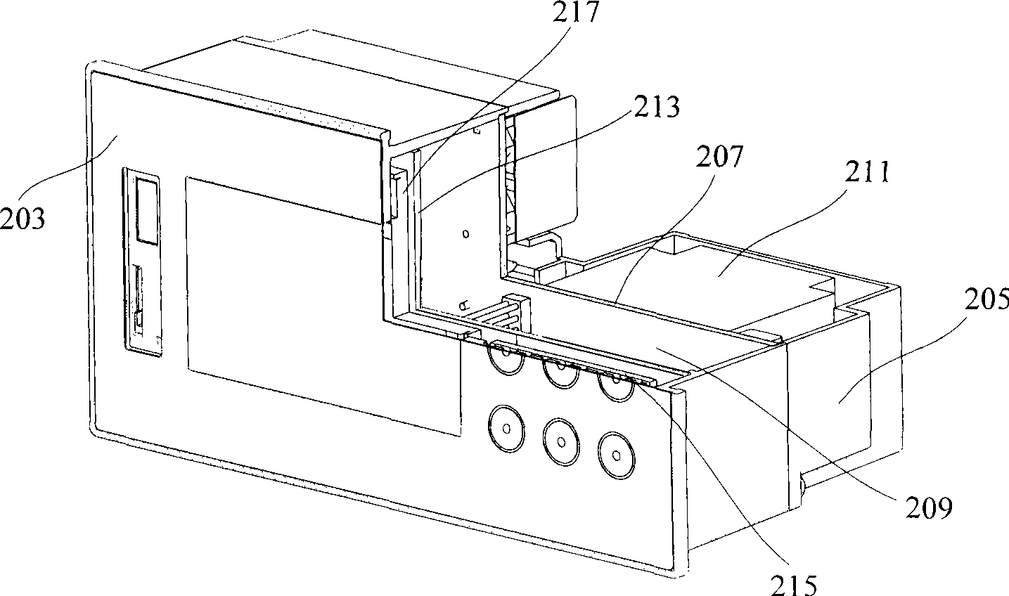
[0036] See figure 2 , which is a schematic diagram of an instrument casing according to an embodiment of the present invention. The instrument case includes a first end housing 203 , a second end housing 205 and a partition plate 207 . The size of the first end shell 203 corresponds to that of the second end shell 205 , and the first end shell 203 and the second end shell 205 form an internal cavity after being connected. The partition plate 207 is disposed between the first end shell 203 and the second end shell 205 , thereby separating the inner cavity into a first end cavity 209 and a second end cavity 211 . Moreover, the first end cavity 209 formed between the partition plate 207 and the first end housing 203 is a sealed space.

[0037] figure 2 The shape of the instrument case is only an embodiment of the present invention, and it can not limit the present...


PUM


Abstract

The invention discloses an instrument shell, which comprises a first end shell, a second end shell and a partition board. The size of the second end shell corresponds to that of the first end shell, and the second end shell is connected with the first end shell to form an inside cavity. The partition board is arranged between the first end shell and the second end shell, the mechanical size of the partition board corresponds to the inside cavity, and the partition board divides the inside cavity into a first end cavity which is used for accomodating various functional circuit boards and is in a sealed state, and a second end cavity which is used for accomodating parts with bigger interference and larger heat productivity. With the structure of the instrument shell, the parts in an instrument are distributed more reasonably, thus the interference existing between the parts is effectively prevented, and the instrument has better heat dissipation effect.

Description

technical field [0001] The invention relates to the technical field of instruments, in particular to a structure of an instrument casing. Background technique [0002] Existing instrument casings are all composed of a casing to form a cavity, and its terminal circuit, control circuit (CPU conditioning circuit, signal conditioning circuit, etc.), drive circuit (such as power supply, etc.) are all located in the same cavity. [0003] Such as the national patent office application number is 97241538.6 patent proposed a kind of on-site display and remote transmission explosion-proof temperature instrument, such as figure 1 As shown, the instrument has an explosion-proof shell 1, and the circuit assembly board is installed in the shell 1, and the liquid crystal display 2 displays the value. , to realize the functions of sensing, transmission and display, and remote transmission integration. [0004] The above-mentioned on-site display and remote transmission explosion-proof tem...

Claims


Application Information

Patent Timeline
IPC IPC(8): G12B9/02
Inventor 丁云李资庭马辉朱丽萍
Owner ZHEJIANG SUPCON INSTR
Why Eureka
Try Eureka