Drive mechanism for a furniture part which is mounted movably in or on an item of furniture

A technology of driving mechanism and furniture parts, which is applied in furniture parts, switches with brake parts, wing fan parts, etc., can solve problems such as inability to guarantee

Active Publication Date: 2009-05-20
JULIUS BLUM GMBH
View PDF0 Cites 12 Cited by
  • Summary
  • Abstract
  • Description
  • Claims
  • Application Information

AI Technical Summary

Problems solved by technology

With this cushioned pull-in device, although collisions of the movable furniture part against the furniture or on the furniture part can be avoided, the secure and at the same time protective locking of the locking element of the drive is achieved by means of a type of energy storage. The cushioned pull-in device that engages after the lock is not guaranteed

Method used


Image

  • Drive mechanism for a furniture part which is mounted movably in or on an item of furniture
  • Drive mechanism for a furniture part which is mounted movably in or on an item of furniture
  • Drive mechanism for a furniture part which is mounted movably in or on an item of furniture

Examples


Embodiment Construction

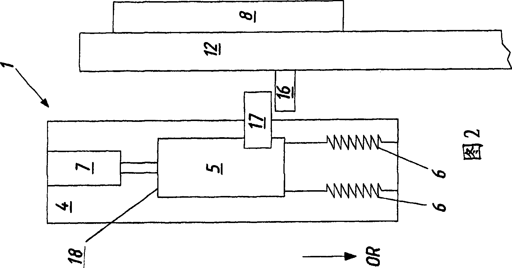
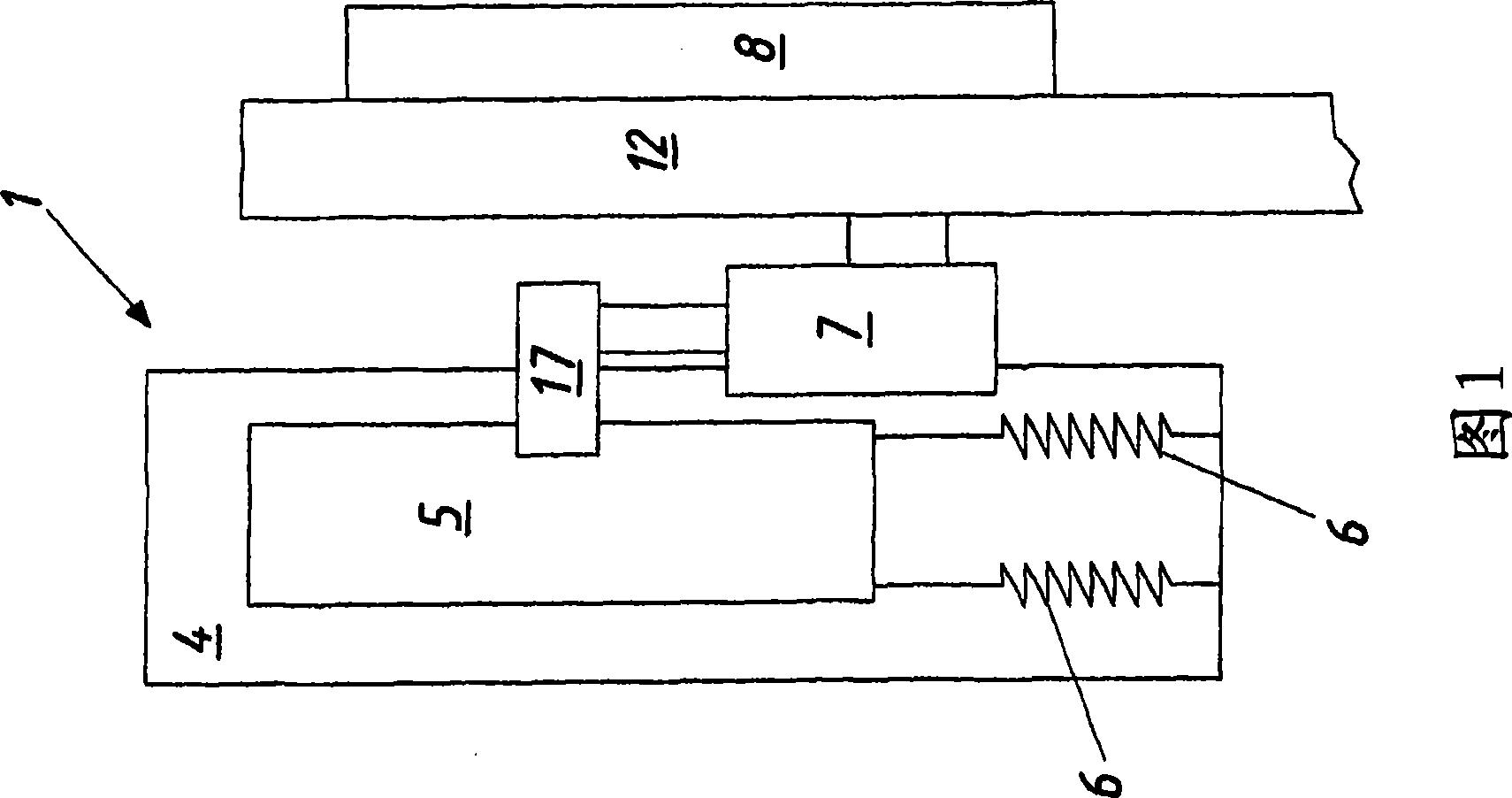
[0034] In the first embodiment of the drive mechanism 1 according to the invention shown in FIG. 1, both the base 4 and the pull-in device 8 are arranged in a fixed position on a piece of furniture not shown, for example when a drawer is pulled out. On the guide rail of the furniture body of the guide system, the drive mechanism 5 can move linearly relative to the base. The lockable drive 5 functions according to the known touch-and-latch principle and is acted upon by an energy store 6 , which in the exemplary embodiment shown is formed by two tension springs. Furthermore, the drive device 5 has a stop element 17 for coupling the drive device 5 to a movable furniture part, also not shown.

[0035] The movable furniture part is movably supported in the furniture by the drawer rail 12 of a drawer pull-out guide system, wherein the coupling of the drawer rail 12 to the stop element 17 of the drive device 5 takes place via a drive element, which in this first embodiment In the exa...


PUM


Abstract

Drive mechanism (1) for a furniture part (3), in particular a drawer or a door, which is mounted movably in or on an item of furniture (2), having a drive apparatus (5) which is guided movably with respect to a base (4) and is loaded by a force accumulator (6), having a damping apparatus (7) and a pulling-in apparatus (8), wherein the drive apparatus (5) has a pushing-out element (9) for moving the furniture part (3) from a closed end position (E) into an open position and a locking element (10) which is guided by a preferably heart-shaped guide track (11) which is formed on the base (4), and wherein the damping apparatus (7), the force accumulator (6) which loads the drive apparatus (5) and the pulling-in apparatus (8) are connected in series.

Description

technical field [0001] The invention relates to a drive mechanism for a furniture part, in particular a drawer or a door, which is movably mounted in or on a piece of furniture, comprising a movable guide relative to a base, loaded by an energy store Drive device, a damping device and a pull-in device, wherein the drive device has a push-out element for moving the furniture part from the closed end position into the open position and a guide rail formed on the base, preferably heart-shaped Guided locking element. Background technique [0002] In drive mechanisms of this type known from the prior art, it is customary for a drive device, which is usually provided on the furniture body, to be coupled to the movable furniture part in order to charge the energy store. In this case, an energy store, which is usually designed as a spring, stores energy over a section of the closing path, wherein the energy necessary for this can be applied manually by the user. The problem found ...

Claims


Application Information

Patent Timeline
Patent Type & Authority Applications(China)
IPC IPC(8): A47B88/04
CPCE05F3/108A47B88/0477E05Y2201/22E05Y2800/00E05Y2201/232E05F5/02E05Y2201/244A47B88/0481E05F1/105E05Y2900/00E05Y2201/488E05Y2900/20A47B2210/0094A47B88/463A47B88/47E05Y2800/11
Inventor H·菲茨
Owner JULIUS BLUM GMBH
Why Eureka
Try Eureka