Manufacture method of power transmission chain

A technology of power transmission and manufacturing method, applied in the field of power transmission chain manufacturing, can solve the problems of reducing the power transmission efficiency of the chain and increasing the bending moment of the chain, etc.

Inactive Publication Date: 2009-05-27
JTEKT CORP
View PDF0 Cites 0 Cited by
  • Summary
  • Abstract
  • Description
  • Claims
  • Application Information

AI Technical Summary

Problems solved by technology

In the chain assembled in this state, frictional resistance occurs on the contact surfaces of the link plates when bending, so the bending moment of the chain may increase, and the power transmission efficiency of the chain may decrease.

Method used


Image

  • Manufacture method of power transmission chain
  • Manufacture method of power transmission chain
  • Manufacture method of power transmission chain

Examples


Embodiment Construction

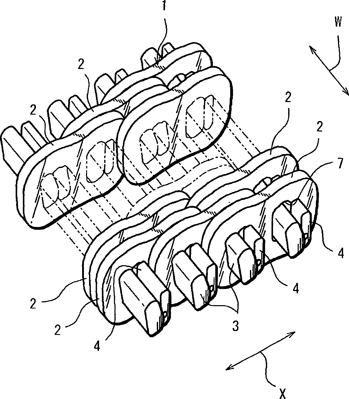
[0035] Preferred embodiments of the present invention will be described with reference to the drawings. figure 1 It is a perspective view typically showing the configuration of a main part of a power transmission chain (hereinafter, simply referred to as a chain) employed in the chain-type continuously variable transmission according to the first embodiment of the present invention. refer to figure 1 , the chain 1 includes: a plurality of link plates 2 arranged in the chain advancing direction X and the width direction W of the chain; a plurality of chain pins 3 for interconnecting these link plates 2; slightly shorter than the chain pins 3 Multiple narrow strips of 4.

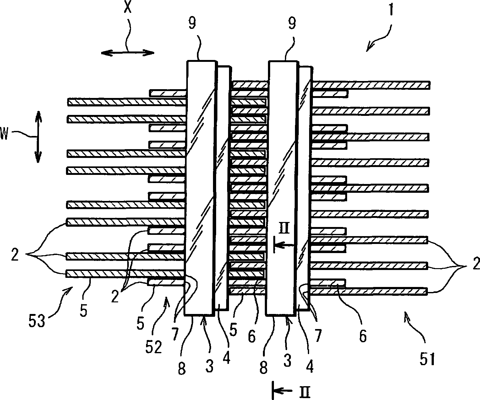
[0036] figure 2 yes means figure 1 The shown cross-sectional view of the main part of the chain 1 shows three sets of link plate groups including a plurality of link plates 2 at the same positions in the chain advancing direction X. As shown in FIG. Specifically, the first link plate group 51 , the second...


PUM


Abstract

A power transmission chain of the invention includes: plural link plates individually including through-holes and arranged in a chain advancing direction and a chain widthwise direction and with predetermined spacing; and plural pins inserted through the through-holes for flexibly interconnecting the link plates. Since the link plates are arranged in the chain widthwise direction with the predetermined spacing, a respective pair of adjoining link plates are prevented from coming into friction contact with each other during the operation of the power transmission chain. Hence, the power transmission chain may be prevented from suffering the decrease of power transmission efficiency.

Description

technical field [0001] The present invention relates to a power transmission chain used in a chain-type continuously variable transmission of a vehicle or the like, a manufacturing method thereof, and a power transmission device using the power transmission chain. Background technique [0002] As a continuously variable transmission (CVT: Continuously Variable Transmission) of an automobile, for example, there is a transmission having: a driving pulley provided on the engine side; a driven pulley provided on the driving wheel side; An endless power transmission chain of a plurality of link plates and a plurality of chain pins interconnecting the link plates. In such a so-called chain-type continuously variable transmission, some sliding contact is made in the circumferential direction of the sheave surface through the conical sheave surface of each pulley and a part of the chain constituent members such as the chain pin end surface of the chain. To generate traction, and th...

Claims


Application Information

Patent Timeline
Patent Type & Authority Applications(China)
IPC IPC(8): F16G13/00F16G13/04F16G5/16F16G5/18
Inventor 安原伸二镰本繁夫福井伸树奥本正典布施贤
Owner JTEKT CORP
Why Eureka
Try Eureka