
Chain

A chain and chain link technology, applied in the field of structural improvement, to achieve the effects of increasing bending resistance, suppressing string vibration, and suppressing back bending

Inactive Publication Date: 2012-05-16
BORGWARNER INC
View PDF9 Cites 3 Cited by
  • Summary
  • Abstract
  • Description
  • Claims
  • Application Information

AI Technical Summary

Problems solved by technology

Also, in this case, when the chain is engaged, the flexural movement of the links is not inhibited, and therefore, there is no reduction in power transmission efficiency when the chain is running

Method used


Image

  • Chain
  • Chain
  • Chain

Examples


Embodiment Construction

[0054] Hereinafter, various exemplary embodiments of the present invention will be described based on the accompanying drawings.

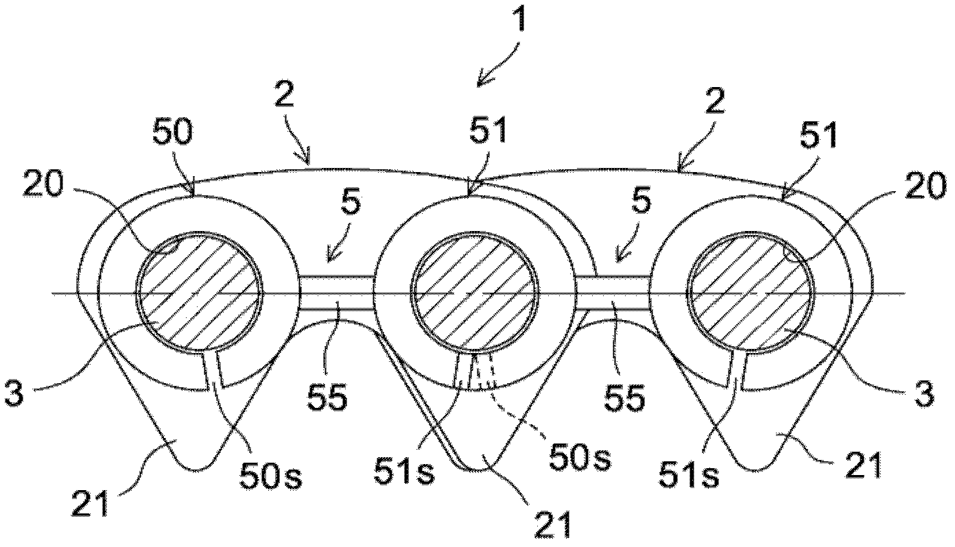
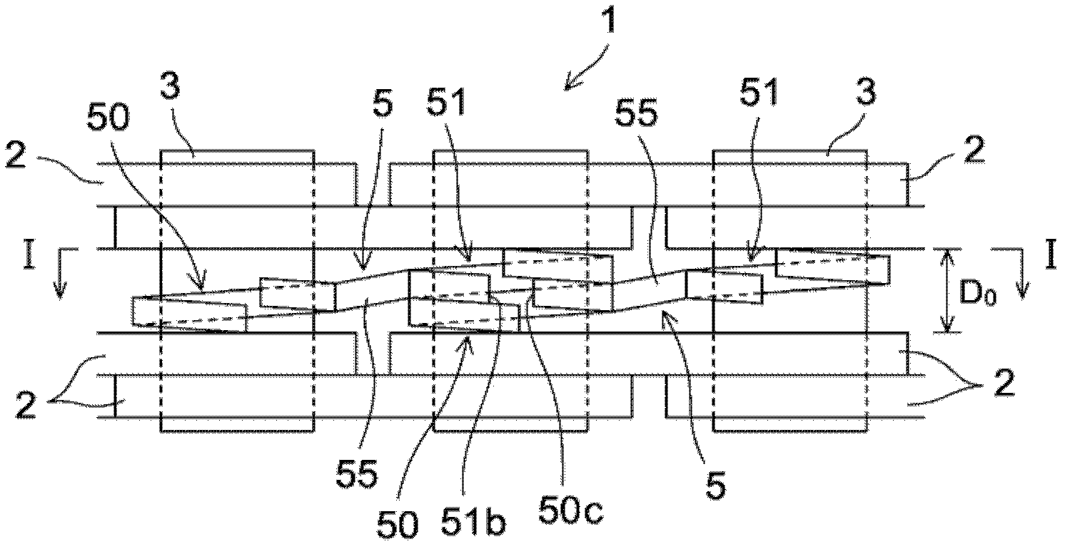
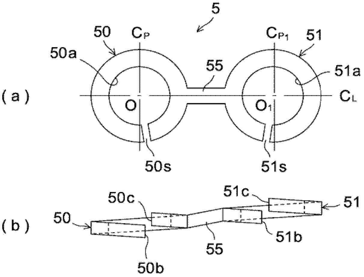
[0055] Figure 1 to Figure 10 A silent chain according to an exemplary embodiment of the present invention is shown, and identical or corresponding components have the same reference symbols in the figures.

[0056] Such as figure 1 and figure 2 As shown, a silent chain 1 has a structure in which a large number of chain plates 2 with pairs of corresponding pin holes 20 and teeth 21 are stacked in the length direction of the chain ( figure 1 and figure 2 in the left-right direction) and the width direction of the chain ( figure 1 in the direction perpendicular to the page; figure 2 In the vertical direction), and the link plates 2 are connected in a manner capable of being flexed around each other by link pins 3 inserted into the pin holes 20 .

[0057] A plurality of spring washer structures 5 serving as a mechanism for preventing backbend...


PUM


Abstract

To provide a chain having a mechanism for preventing backbend which does not cause any reduction in power transmission efficiency when the chain is operating, which can suppress string vibration in the chain spans, and which is highly durable. A mechanism for preventing backbend is provided, in the chain length direction, with a plurality of spring washer structures (5) consisting of a pair of left-right spring washer parts (50, 51) which have linking pins (3) inserted therein, and linking bars (55) for linking the areas between the spring washer parts (50, 51); and adjacent spring washer structures (5) in the chain length direction extend in the length direction of the chain in a state in which the spring washer parts (50, 51) of each are overlapping. When link plates (2) undergo backbend, the spring washer structures (5) flex together with the link plates (2), and the mutual rotation of the spring washer parts (50, 51) causes an increase in the thickness of the spring washer structures (5).

Description

technical field [0001] The present invention relates to a chain provided with a mechanism for preventing backbend in order to accommodate string vibrations within the span of the chain, and more precisely to a method for said mechanism for preventing backbow Improve structure. Background technique [0002] Silent chains or roller chains are used, for example, as power transmission chains and timing chains in automobiles, motorcycles, and the like. These chains generally have a configuration in which a large number of links, including pairs of corresponding pin holes, are correspondingly connected in such a way that the links can be wound around each other by linking pins inserted into each pin hole. flex. [0003] When these kinds of chains are wound around a drive sprocket and a driven sprocket and turned, a tension side span and a slack side span are created in the area between the sprockets where the chain is, but When the chain is running, a resonance is created on th...

Claims


Application Information

Patent Timeline
Patent Type & Authority Applications(China)
IPC IPC(8): F16G13/04F16G13/06F16H7/06
CPCF16G13/04F16G13/18
Inventor 小寺哲二
Owner BORGWARNER INC
Learn More