Image display apparatus and method

An image display device and image technology, which are applied in image communication, static indicators, televisions, etc., can solve the problems of dynamic image pseudo-contour color level confusion, dynamic image blurring, and damage to display quality.

Inactive Publication Date: 2009-05-27
HITACHI LTD
View PDF3 Cites 2 Cited by
  • Summary
  • Abstract
  • Description
  • Claims
  • Application Information

AI Technical Summary

Problems solved by technology

[0002] A display device that divides one field into multiple screens with different luminance weights in the time direction (hereinafter referred to as subfields (SF)), and displays a screen in one field by controlling the light emission and non-light emission of each subfield In , there are the following problems: when displaying dynamic images, the so-called dynamic image quasi-contour color gradation disorder and dynamic image blurring will occur, which will damage the display quality

Method used


Image

  • Image display apparatus and method
  • Image display apparatus and method
  • Image display apparatus and method

Examples


Embodiment 1

[0078] The first embodiment of the present invention is as Figure 9 The image display in the case where the intervals of light emission start times between subfields shown in (a) are equal intervals. In the figure, the horizontal axis represents the image horizontal position and the vertical axis represents time, showing display data when the number N of subfields is six. Furthermore, the interval between the light emission start times between the subfields is constant T0 regardless of the light emission periods E1 , E2 , E3 , E4 , and E5 of the subfields.

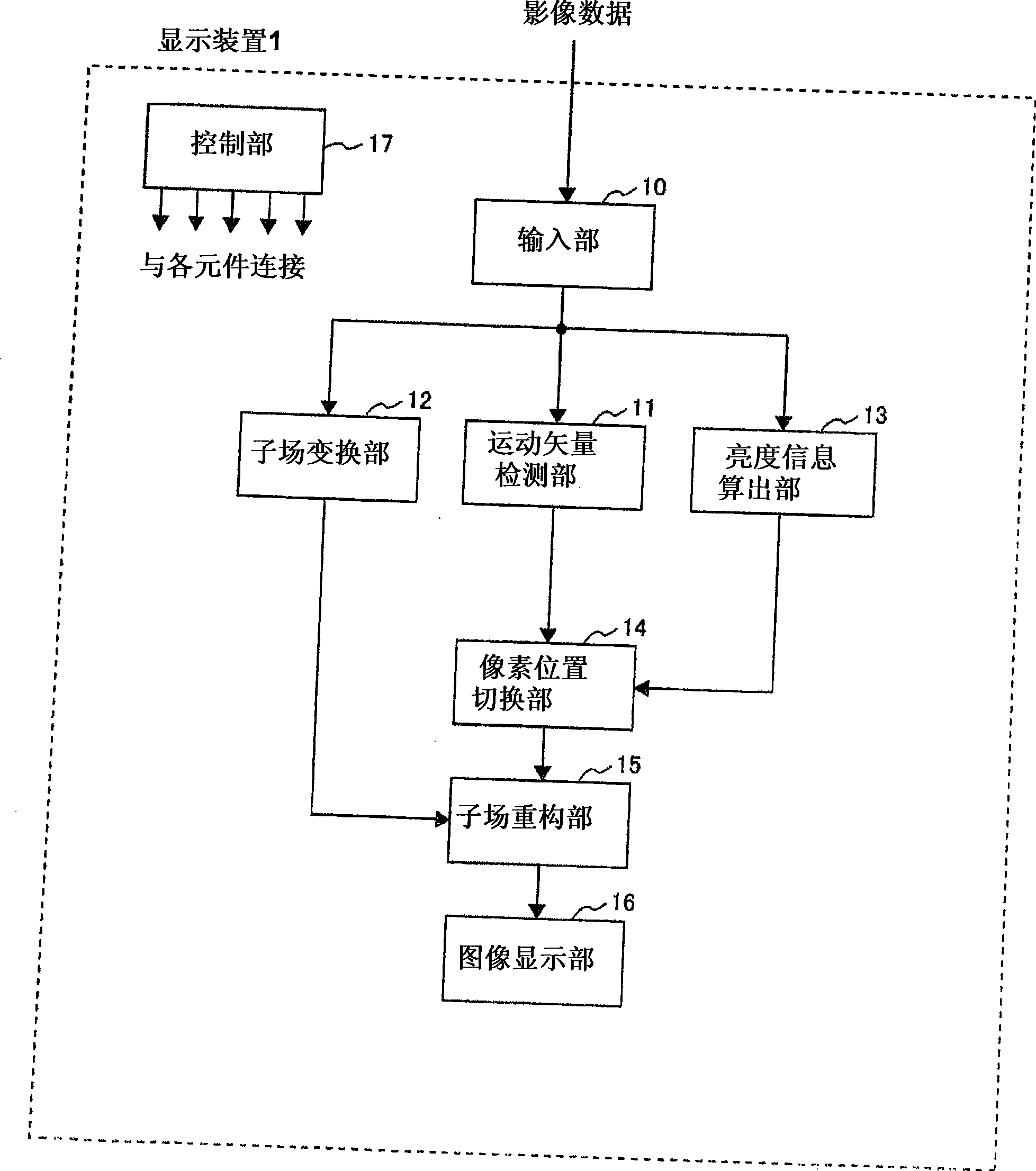
[0079] figure 1 It is a block diagram showing an example of the image display device according to the first embodiment of the present invention. The structure of the image display device 1 includes an input unit 10, a motion vector detection unit 11, a subfield conversion unit 12, a brightness information calculation unit 13, a pixel position switching unit 14, a subfield reconstruction unit 15, an image display unit 1...

Embodiment 2

[0143] The second embodiment of the present invention is as Figure 9 The display method shown in (b) considers the light emission period of the subfield and makes the interval of the light emission start time variable.

[0144] Figure 9 In (b), the time intervals T1, T2, T3, T4, and T5 of the light-emitting start times between the subfields correspond to the light-emitting periods E1', E2', E3', E4', and E5' of each subfield, respectively. variable. Here, variable corresponding to the light-emitting periods E1', E2', E3', E4', E5' means, for example, that the time intervals T1, T2, T3, T4, T5 are determined by the light-emitting periods E1', E2 ', E3', E4', and E5' are determined for the value of the function of each variable. Therefore, unlike the first embodiment, the intervals T1 , T2 , T3 , T4 , and T5 between the light emission start times used in the present embodiment are not the same time length.

[0145] Here, the meaning that the interval of the light emission ...

Embodiment 3

[0193] In the third embodiment of the present invention, an intermediate field between the current field and the previous field is generated, and the sub-field data is reconstructed from the motion vector F whose end point is the pixel of the intermediate field and the starting point is the pixel of the previous field. In addition, as in the above-mentioned first embodiment, the intervals of the light emission start times between the subfields are fixed at equal intervals.

[0194] Figure 14 It is a diagram for explaining the intermediate field and the motion vector F used in this embodiment. The motion vector F is a vector indicating from which pixel of the previous field A the pixels of the middle field B located between the current field C and the previous field A moved. which is, Figure 14 where is a motion vector that ends at pixel b in the middle field and starts at pixel a in the previous field A.

[0195] Here, for the method of generating the intermediate field f...


PUM


Abstract

The invention provides an image display device and method. It is possible to better correct dynamic false contours in gradation display made by dividing each field into plural subfields to prevent image quality deterioration. A motion vector detection section (11) detects a motion vector of corresponding pixels between two mutually neighboring fields. A brightness information calculation section (13) calculates the brightness information of each pixel of the input images. A pixel position changing section (14) calculates a pixel position vector indicating from where to acquire data for use in rearranging emission data by multiplying a motion vector ending at a pixel to be rearranged by a predetermined function. Furthermore, when a brightness difference between the pixel from which data is to be acquired and the pixel to be rearranged is larger than a threshold value, the pixel position changing section corrects the calculated pixel position vector to change the pixel indicated thereby to one closer to the pixel to be rearranged until the brightness difference is equal to or smaller than the threshold value.

Description

technical field [0001] The present invention relates to an image display device and an image display method that divide a field time into a plurality of image displays and perform gradation display. Background technique [0002] A display device that divides one field into multiple screens with different luminance weights in the time direction (hereinafter referred to as subfields (SF)), and displays a screen in one field by controlling the light emission and non-light emission of each subfield In this method, there is a problem that, when displaying a moving image, the so-called pseudo-contour of the moving image is disturbed in gradation and the moving image is blurred, which impairs the display quality. This is known to occur when the human eye tracks moving objects. [0003] In order to prevent the occurrence of the pseudo-contour of the dynamic image, the following method is proposed in Patent Document 1: the motion vector is detected using the display data between fra...

Claims


Application Information

Patent Timeline
Patent Type & Authority Applications(China)
IPC IPC(8): G09G3/20G09G3/28H04N5/66
CPCG09G2360/16G09G2320/0266G09G2320/106G09G3/2022G09G2320/0261
Inventor 服部英春浜田宏一福田伸宏千秋丰高田佳明
Owner HITACHI LTD
Why Eureka
Try Eureka