Electronic image pickup device

A camera device, electronic technology, applied in static cameras, TVs, color TVs, etc., can solve problems such as the problem of undisclosed dust adhesion

Inactive Publication Date: 2006-12-27
OLYMPUS CORP
View PDF1 Cites 0 Cited by
  • Summary
  • Abstract
  • Description
  • Claims
  • Application Information

AI Technical Summary

Problems solved by technology

[0005] In the above-mentioned prior art, there is no disclosure of a treatment method for the problem of dust adhesion when the shutter is opened in such a long exposure time

Method used


Image

  • Electronic image pickup device
  • Electronic image pickup device
  • Electronic image pickup device

Examples


no. 1 Embodiment approach

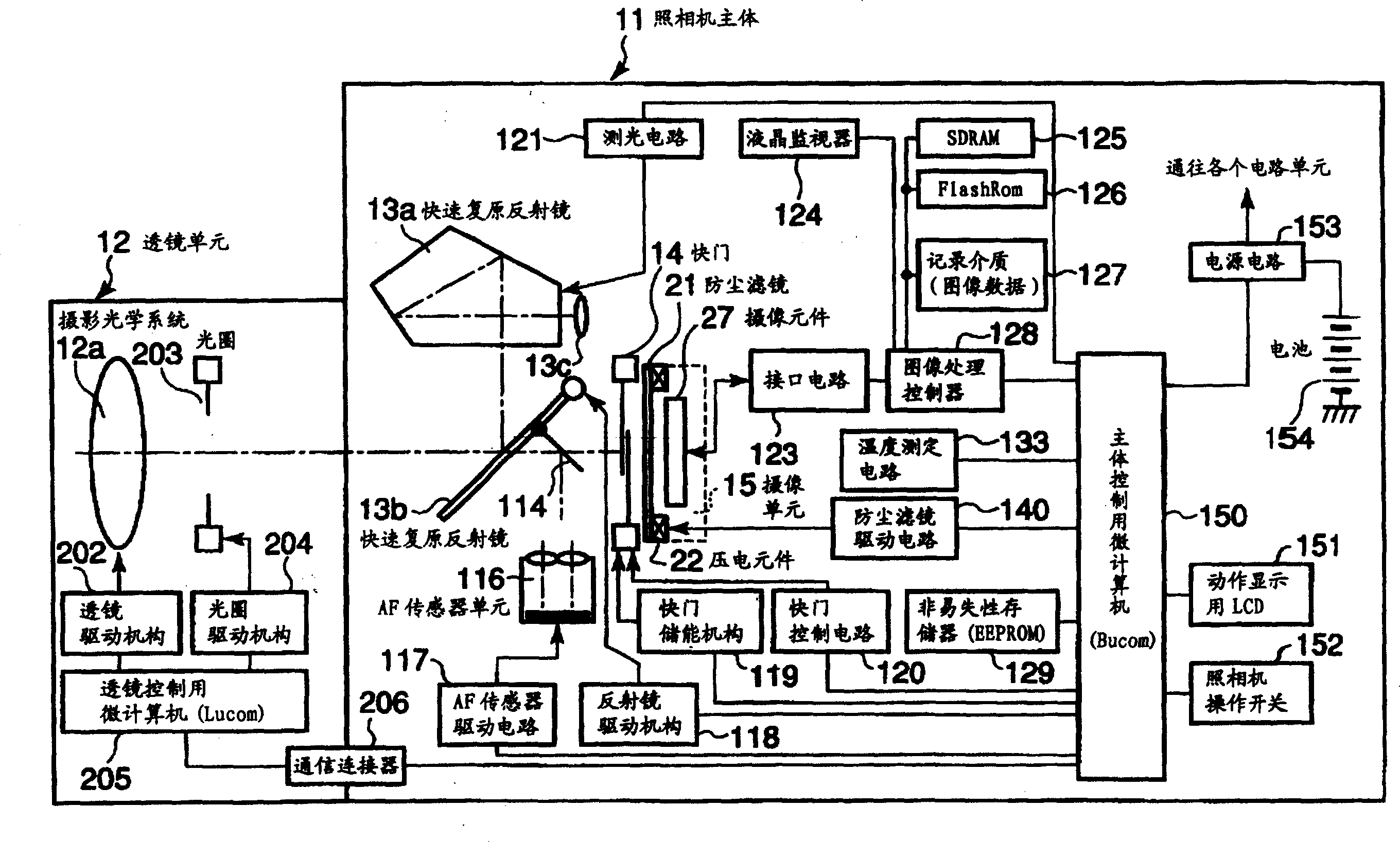
[0182] Figure 13 It is a flowchart for explaining the operation of Bucom 150 in the camera system according to the first embodiment of the present invention.

[0183] If the power switch of the camera is turned on (ON), the Bucom150 starts to work. In step S100, processing for starting the camera system is performed. The power supply circuit 153 is controlled to supply power to each circuit unit constituting the camera system. In addition, the initial setting of each circuit is performed.

[0184] Step S101 is an operation step for detecting the state of the lens unit 12 through a communication operation with Lucom 205 , and is executed periodically. If it is detected in step S102 that the lens unit 12 has been attached to the camera body 11, the process proceeds from step S102 to step S103. In step S103, the two piezoelectric elements 22a and 22b provided on the dustproof filter 21 are driven in phase at the resonance frequency (f0) for a predetermined time (T0). In ord...

no. 2 Embodiment approach

[0210] Figure 17 It is a flowchart for explaining the operation of Bucom 150 in the camera system according to the second embodiment of the present invention. The second embodiment is characterized in that the subroutine "imaging operation" described in the first embodiment ( Figure 13 In step S119), the dustproof filter 21 is driven intermittently. Other steps are the same as in the first embodiment.

[0211] First, in step S400, the status of the dust-proof permission flag is detected. If the dustproof permission flag is "1", go to step S401 to start the vibrating action of the dustproof filter 21. In step S401 , a predetermined drive signal is applied to the piezoelectric elements 22 a , 22 b that vibrate the dustproof filter 21 . After that, go to step S402.

[0212] On the other hand, if the dustproof permission flag is "0" at step S400, then immediately go to step S402. In step S402, the image processing controller 128 is instructed to start the imaging operation...

no. 3 Embodiment approach

[0217] Figure 18 It is a flowchart for explaining the operation of Bucom 150 in the camera system according to the third embodiment of the present invention. The third embodiment is characterized in that the subroutine "imaging operation" described in the first embodiment ( Figure 13 In step S119), traveling waves are used to drive the dustproof filter 21. Other steps are the same as in the first embodiment.

[0218] First, in step S300, the status of the dustproof permission flag is determined. If the flag is "1", go to step S301 to start the vibrating action of the dustproof filter 21 . In step S301, drive signals having a frequency (fs) and a phase of 90° are applied to the two piezoelectric elements 22a and 22b. Through this action, such as Figure 10 As shown, traveling waves are generated in the dust filter 21 . By selecting a driving method with a small amount of deformation of the dust filter 21 , it is possible to suppress an increase in aberration caused by t...


PUM


Abstract

Provided is an electronic imaging apparatus which does not bring about a deterioration in picture quality and in which wasteful power consumption is eliminated. The electronic imaging apparatus is equipped with a photographic optical system which forms the optical image of a subject, an imaging device which converts the optical image into an electric signal, a dust-proof filter which is arranged between the photographic optical system and the imaging device and which prevents dust or the like from being deposited on the photoelectric conversion surface of the imaging device and a microcomputer which makes the dust-proof filter perform a dust removing operation by vibrating the filter at prescribed frequencies and the computer vibrates the filter in a first vibration mode in timing corresponding to the start of an imaging operation and vibrates the filter in a second vibration mode in timing corresponding to the exchanging of the photographic optical system.

Description

technical field [0001] The present invention relates to an electronic imaging device, and more particularly, to an electronic imaging device having a dustproof function capable of removing dust adhering to components such as a camera system. Background technique [0002] Conventionally, as an example of a technique related to the dustproof function of an optical device, a technique of vibrating a cover glass (dustproof glass) protecting an imaging element to shake off dust adhering to the dustproof glass has been proposed. For example, there is a technique disclosed in Japanese Patent Laid-Open No. 2002-204379 in which a piezoelectric element is used as a unit for vibrating the dustproof glass. The piezoelectric element expands and contracts in response to the applied voltage, and vibrates the attached dustproof glass at a predetermined cycle. [0003] Various situations in which dust adheres to the dustproof glass can be imagined. When replacing the taking lens, there is ...

Claims


Application Information

Patent Timeline
Patent Type & Authority Patents(China)
IPC IPC(8): H04N5/225G03B17/02G03B19/02G03B7/00G03B7/20G03B17/14H04N101/00
Inventor 伊藤顺一
Owner OLYMPUS CORP
Why Eureka
Try Eureka