Ultrasonic matching layer and transducer
A technology of ultrasonic transducers and matching layers, which can be used in sound-generating devices, ultrasonic/acoustic/infrasonic diagnosis, instruments, etc., and can solve difficult imaging problems
- Summary
- Abstract
- Description
- Claims
- Application Information
AI Technical Summary
Benefits of technology
Problems solved by technology
Method used
Image
Examples
Embodiment 1
[0084] Example 1: Exemplary LiNb 20MHz to 25MHz Transducer with TPX Lens Laminate Manufacturing
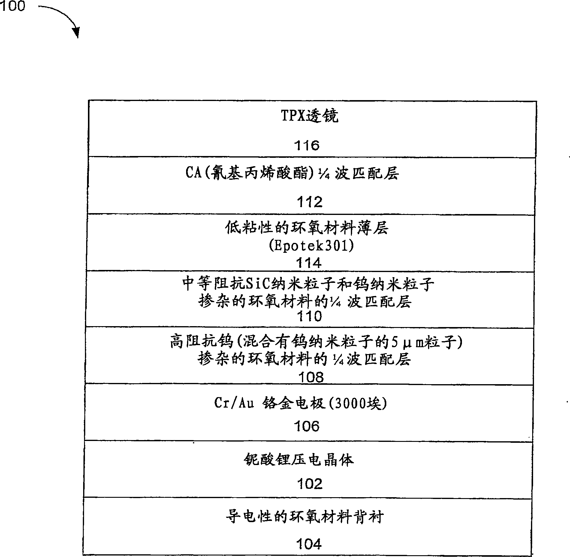
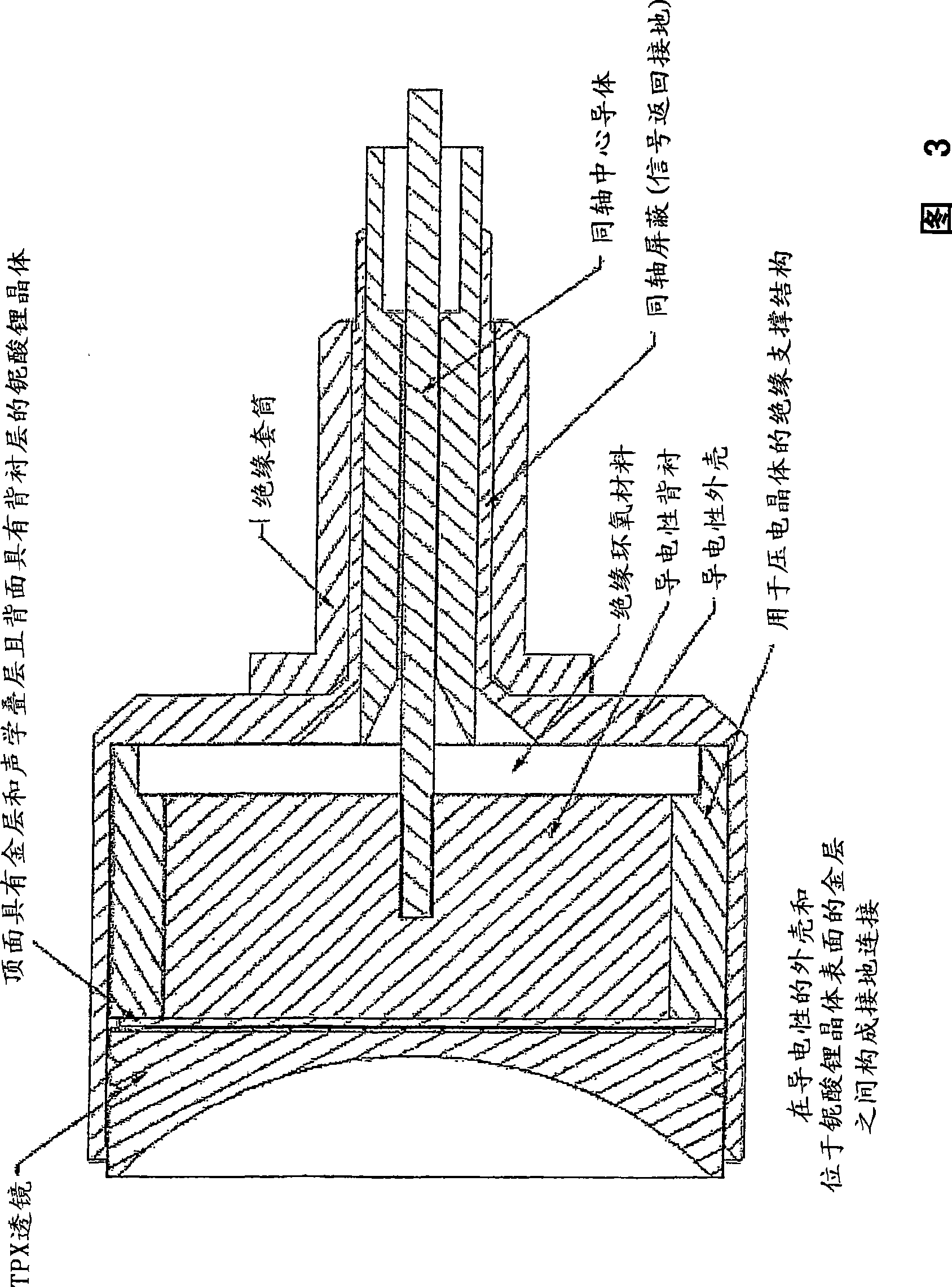
[0085] 5 is a block diagram illustrating an exemplary method of fabricating an exemplary Li Nb 20MHz to 25MHz transducer with a TPX lens. The fabrication process is described below in three exemplary sections. First, the fabrication of matching and piezoelectric layers to form a stack is described. Second, the fabrication of the lens layer and cyanoacrylate matching layer is described. Finally, the process of bonding the lens and cyanoacrylate layer to the transducer stack is described.
[0086] Fabrication of matching and piezoelectric layers
[0087] Lithium niobate crystals are prepared for the piezoelectric layer, as shown in block 504 . A 36° Y-cut LiNb crystal was ground (lap) to a thickness of 0.4λ at the desired center frequency to compensate for mass loading. The crystal is plated with 3000 Angstroms of gold using suitable means such as electron beam deposition...
Embodiment 2
[0129] Example 2: For an exemplary broadband (85% to 95% of -6dB bandwidth) general high-frequency design of lithium niobate transducer
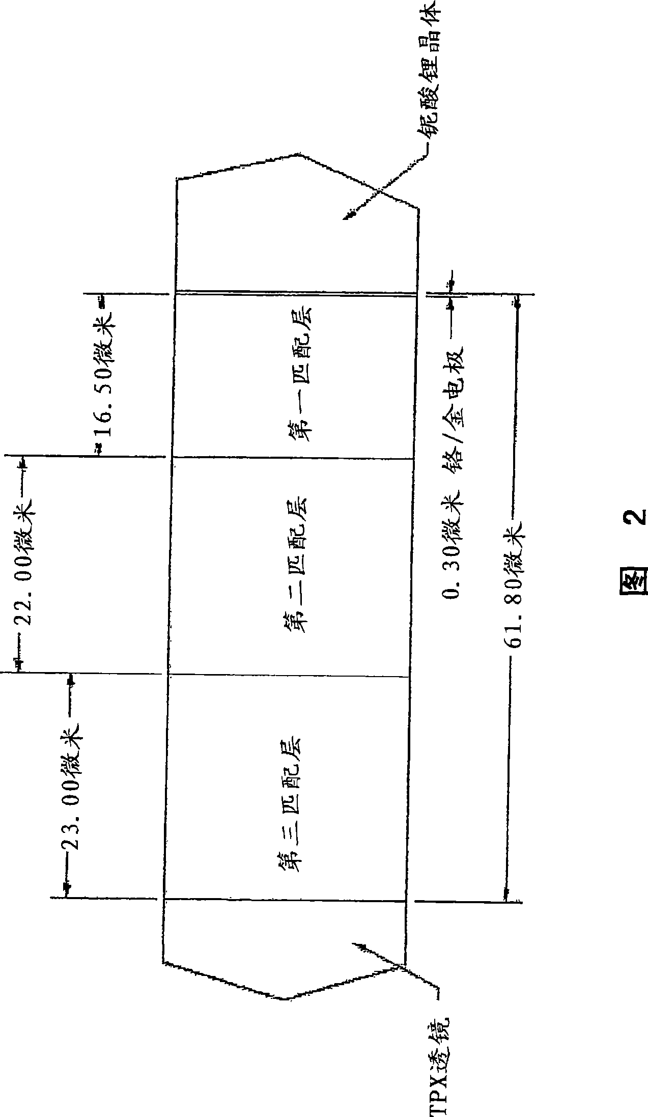
[0130] Table 1 shows the different layers that make up an exemplary transducer stack. This stack design can be used for transducers with center frequencies from 20 MHz to over 60 MHz.
[0131] Select the design center frequency f D , making it higher than the desired operating center frequency of the device f 0 , to compensate for mass loading that lowers the center frequency of the device. f D is the frequency at which the device operates in air without a lens and an air backing. For this exemplary design, f D is chosen to be approximately 1.15 to 1.25 times the desired center frequency of the final transducer. For example, for a 20MHz device, given the relationship shown in Table 1, one would choose f D = about 23MHz to 25MHz.
[0132] Table 1:
[0133]
PUM
| Property | Measurement | Unit |
|---|---|---|
| Thickness | aaaaa | aaaaa |
| Mass density | aaaaa | aaaaa |
| Mass density | aaaaa | aaaaa |
Abstract
Description
Claims
Application Information
 - R&D
- Intellectual Property
- Life Sciences
- Materials
- Tech Scout
- Unparalleled Data Quality
- Higher Quality Content
- 60% Fewer Hallucinations
Browse by: Latest US Patents, China's latest patents, Technical Efficacy Thesaurus, Application Domain, Technology Topic, Popular Technical Reports.
© 2025 PatSnap. All rights reserved.Legal|Privacy policy|Modern Slavery Act Transparency Statement|Sitemap|About US| Contact US: help@patsnap.com


