
Variable capacity compressor

A compressor and capacity technology, applied in the direction of liquid variable capacity machinery, mechanical equipment, machines/engines, etc., can solve the problems of zero discharge flow, smaller stroke, less discharge flow, etc., and achieve the effect of maintaining the inclination angle

Inactive Publication Date: 2009-06-10
CALSONIC KANSEI CORP
View PDF1 Cites 2 Cited by
  • Summary
  • Abstract
  • Description
  • Claims
  • Application Information

AI Technical Summary

Problems solved by technology

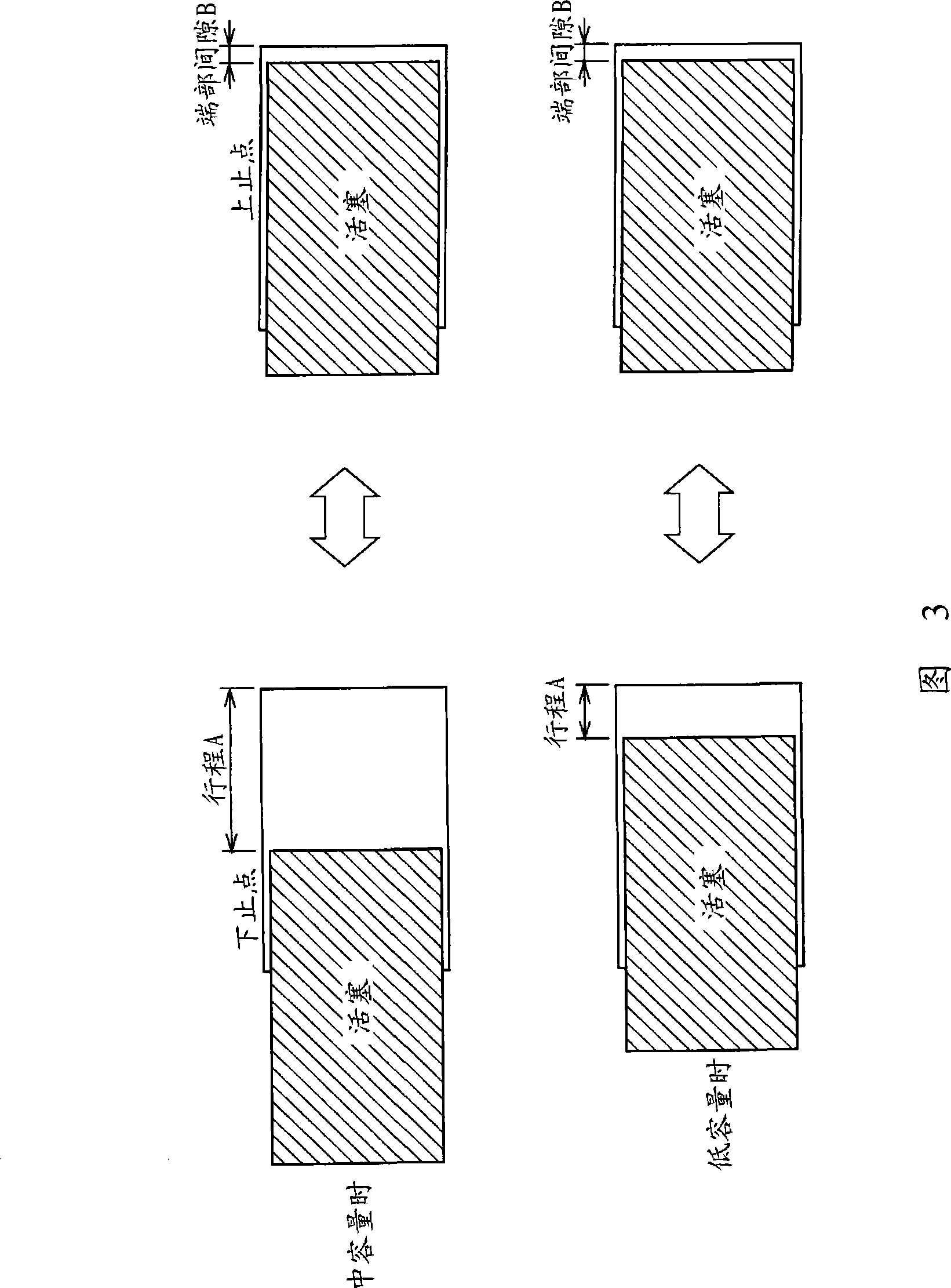
Also, as the approach to the minimum capacity increases the end gap, the stroke naturally decreases, so the ratio of the dead volume to the discharge capacity increases sharply, and at a certain swash plate angle Phenomenon in which the discharge flow rate from the cylinder chamber 106 drops sharply to zero
The low discharge capacity area originally refers to an unstable area in which the discharge flow rate is small. Therefore, when the discharge flow rate undergoes such a sudden change, there is a problem that the inclination angle of the swash plate 113 cannot be stably maintained.

Method used


Image

  • Variable capacity compressor
  • Variable capacity compressor
  • Variable capacity compressor

Examples


Embodiment Construction

[0029] Embodiments of the present invention will be described below with reference to the drawings.

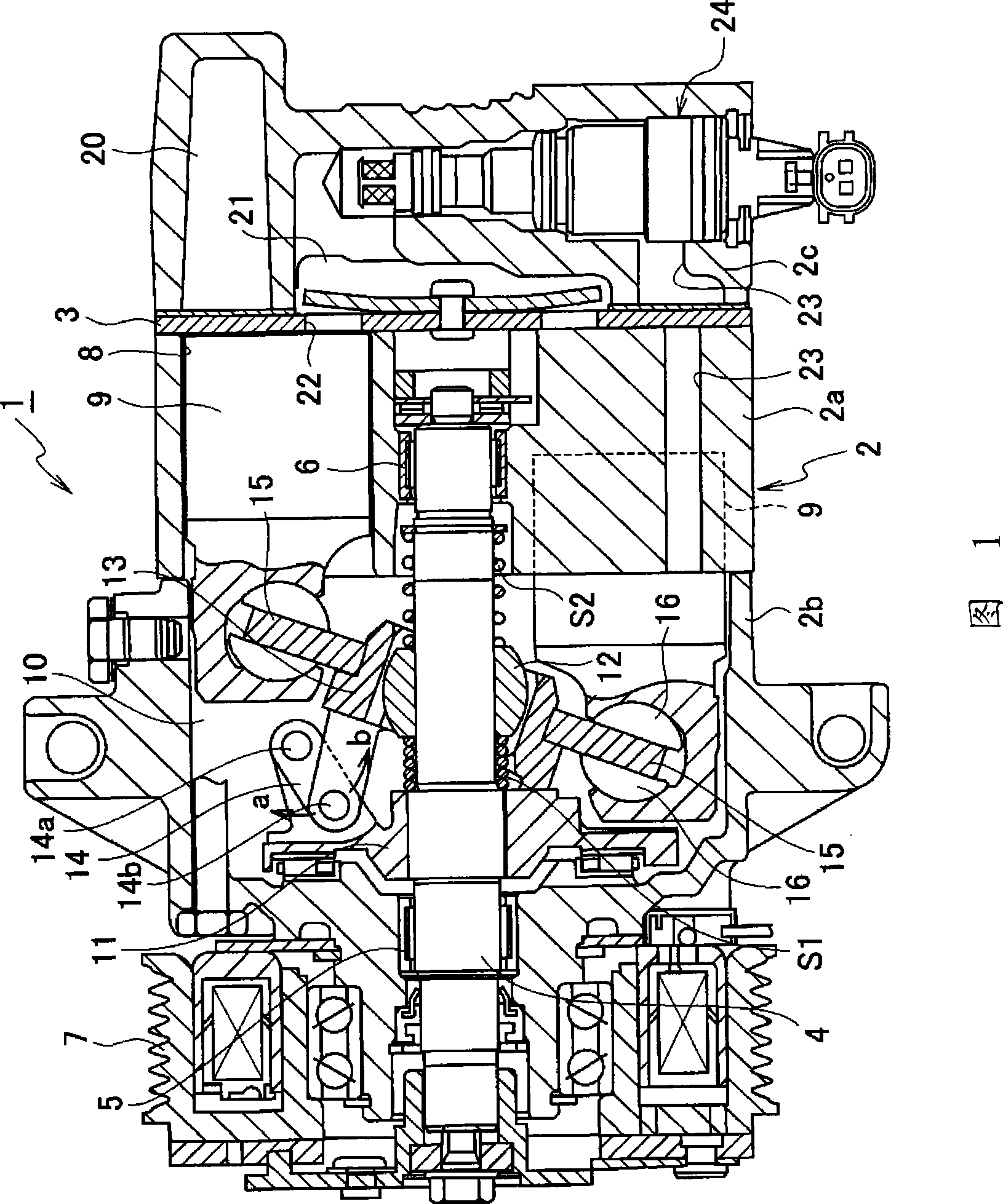
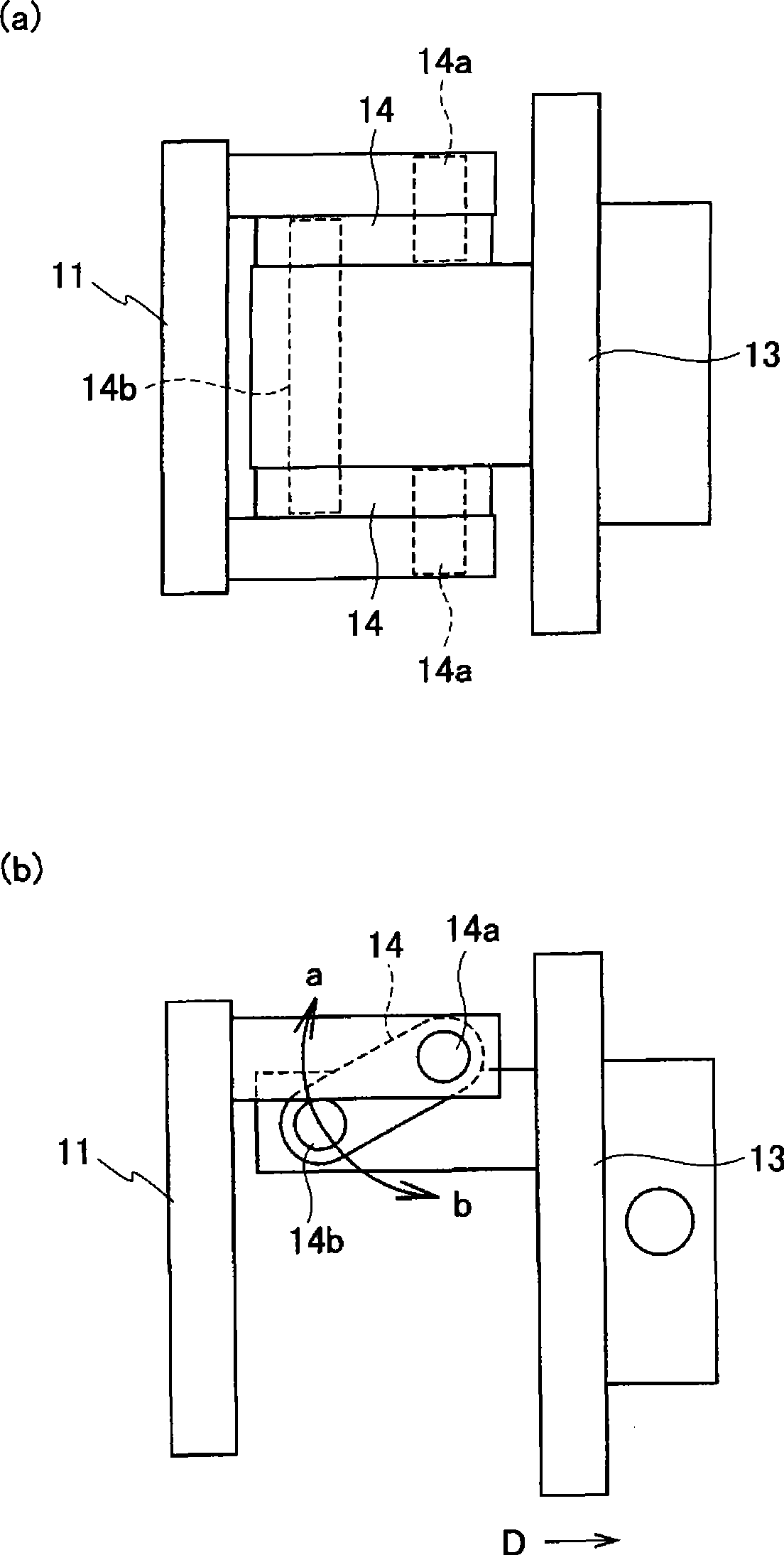
[0030] 1 to 4 show an embodiment of the present invention, and FIG. 1 is an overall cross-sectional view of a variable capacity compressor, figure 2 (a) is a schematic plan view showing the connected state of the connecting rod, figure 2 (b) is a schematic side view showing the connected state of the connecting rod, FIG. 3 is a graph for explaining the stroke ratio, and FIG. 4 is a characteristic graph showing the relationship between the discharge capacity and the end gap.

[0031] As shown in FIG. 1 , a variable capacity compressor 1 has a casing 2 . The housing 2 is assembled from a cylinder block 2a, a front head portion 2b disposed on one side of the cylinder block 2a, and a rear head portion 2c disposed on the other side of the cylinder block 2a via a valve body 3. As shown in FIG.

[0032]A drive shaft 4 penetrating through a crank chamber 10 described below is arra...


PUM


Abstract

The invention provides a variable capacity compressor, which can prevent discharge rate from suddenly dropping to zero in a low discharge capacity region to the maximum and can stably maintain the inclination angle of a swash plate. The variable capacity compressor (1) connects a rotor (11) fixed on a drive shaft (4) and a shaft journal (13) by means of a connecting bar (14). The connecting bar (14) rotates and centers around the rotor (11). The rotation can simultaneously change the inclination angles of the shaft journal (13) and the swash plate (15). The reciprocating stroke of each piston (9) can be changed according to the inclination angle of the swash plate (15). The connecting bar (14) and the rotor (11) are connected at a first rotary fulcrum portion (14a) and the connecting bar (14) and the shaft journal (13) are connected at a second rotary fulcrum portion (14b) so that the first rotary fulcrum portion (14a) is positioned at the side of the shaft journal (13) and the second rotary fulcrum portion (14b) is positioned at the side of the rotor (11).

Description

technical field [0001] The present invention relates to a variable capacity compressor which can change the discharge capacity of a piston by utilizing the inclination angle of a swash plate. Background technique [0002] As such a conventional variable capacity compressor, there is a compressor disclosed in Patent Document 1. As shown in FIG. [0003] As shown in FIG. 5 , this variable capacity compressor 100 has a casing 101 . The housing (housing) 101 is mainly composed of a cylinder block 101a, a front head portion (front head) 101b disposed on one end side of the cylinder block 101a, and a rear head portion (front head) disposed on the other end side of the cylinder block 101a via a valve plate 102. rear head) 101c assembled. [0004] A drive shaft 103 is disposed at the center of the housing 101 . Both ends of the drive shaft 103 are rotatably supported by the housing 101 via radial bearings 104 and 105 . [0005] In the cylinder block 101a, a plurality of cylinder...

Claims


Application Information

Patent Timeline
Patent Type & Authority Applications(China)
IPC IPC(8): F04B27/12F04B27/18
CPCF04B27/1072F04B27/18F04B27/08F04B25/04
Inventor 宫地俊胜
Owner CALSONIC KANSEI CORP
Learn More