Dispersion strip forming method

A technique of scattering strips and together, applied in the field of resolution enhancement, can solve problems affecting the quality of lithography patterns

Inactive Publication Date: 2009-06-10
SEMICON MFG INT (SHANGHAI) CORP
View PDF0 Cites 5 Cited by
  • Summary
  • Abstract
  • Description
  • Claims
  • Application Information

AI Technical Summary

Problems solved by technology

[0004] The technical problem to be solved by the present invention is to provide a method for generating scattering strips, so as to avoid the problem that the randomness of the scattering strips in the key pattern part of the main pattern of the photomask is shortened or cleared, which affects the quality of the photolithographic pattern.

Method used


Image

  • Dispersion strip forming method
  • Dispersion strip forming method
  • Dispersion strip forming method

Examples


Embodiment Construction

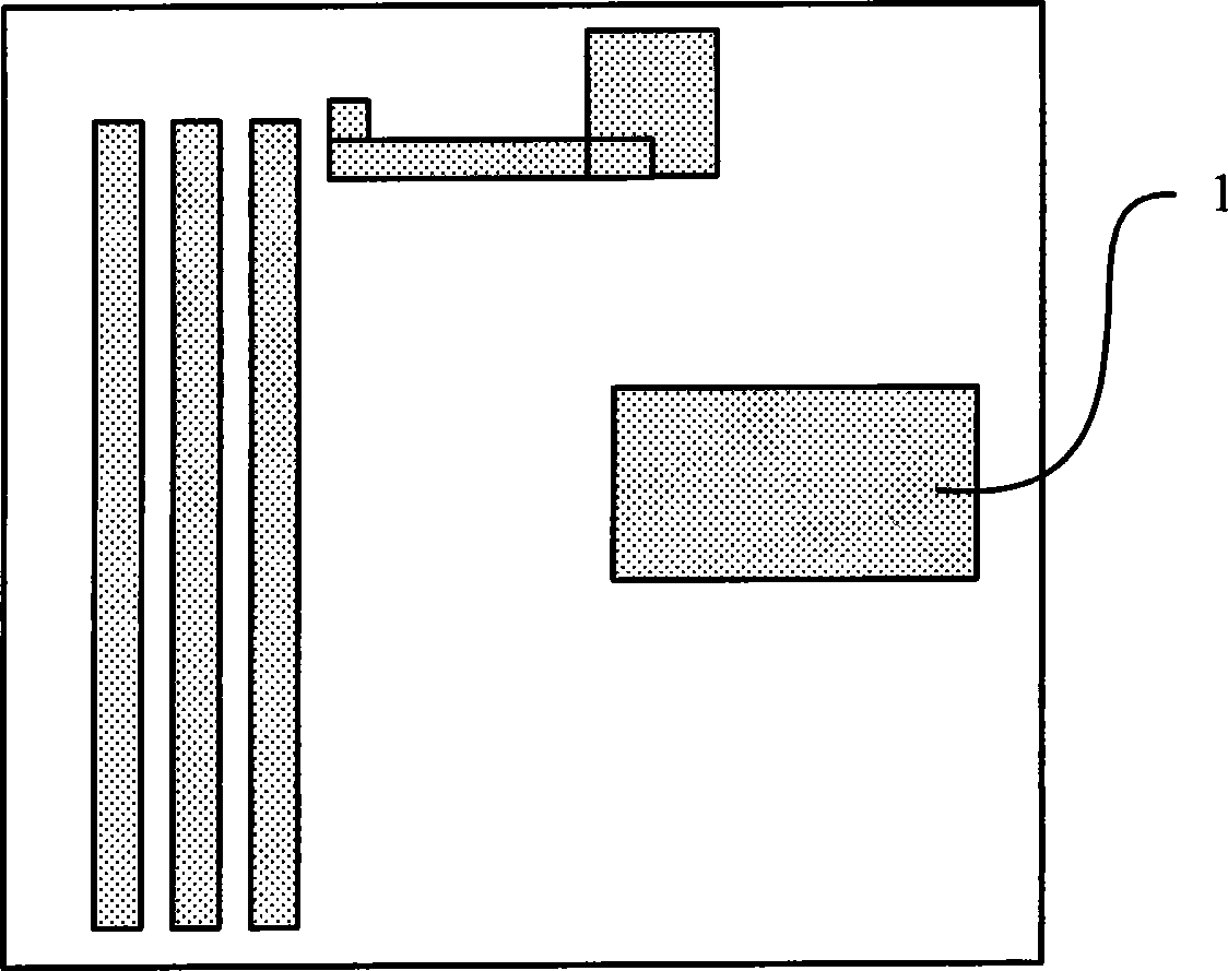
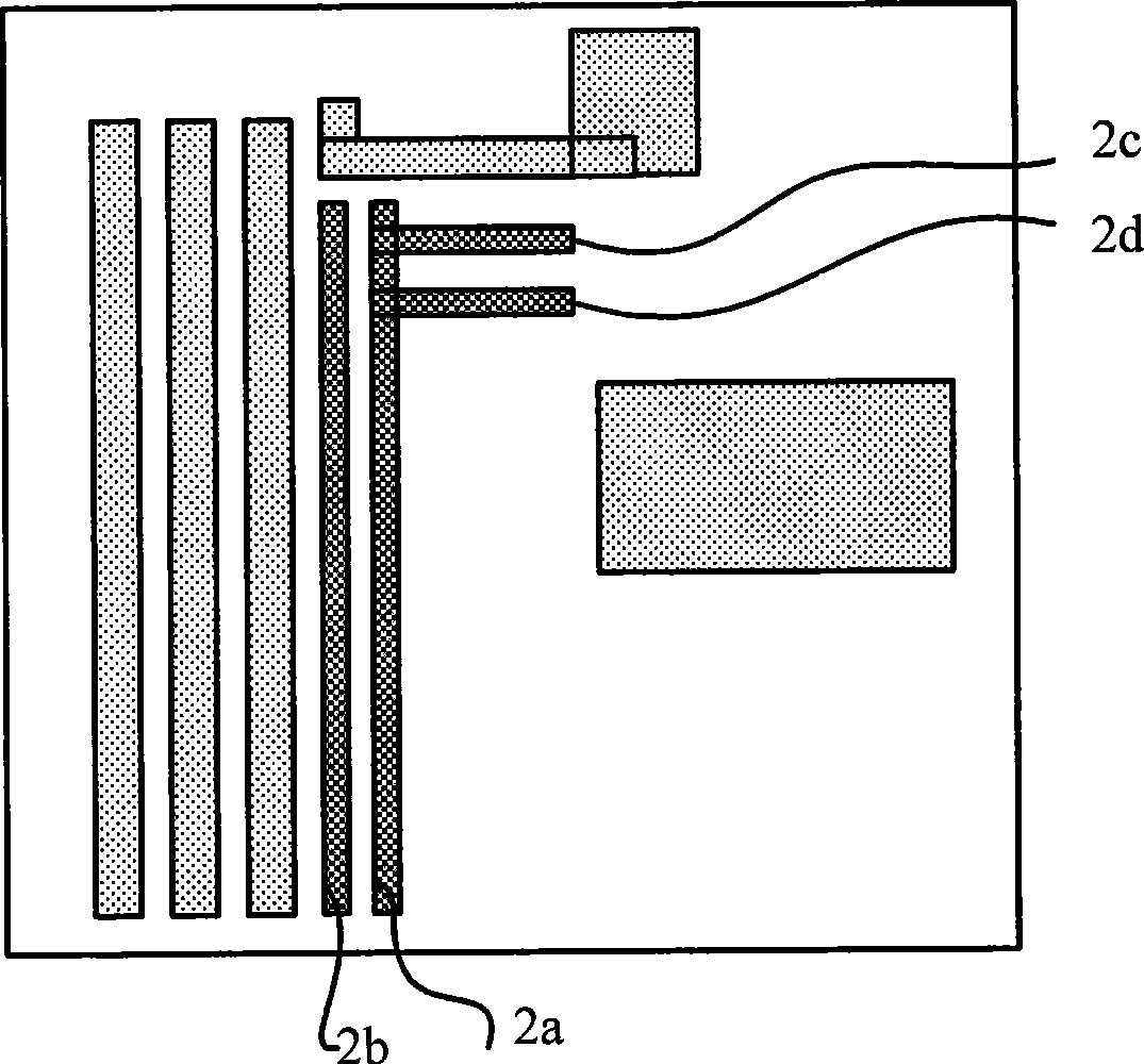
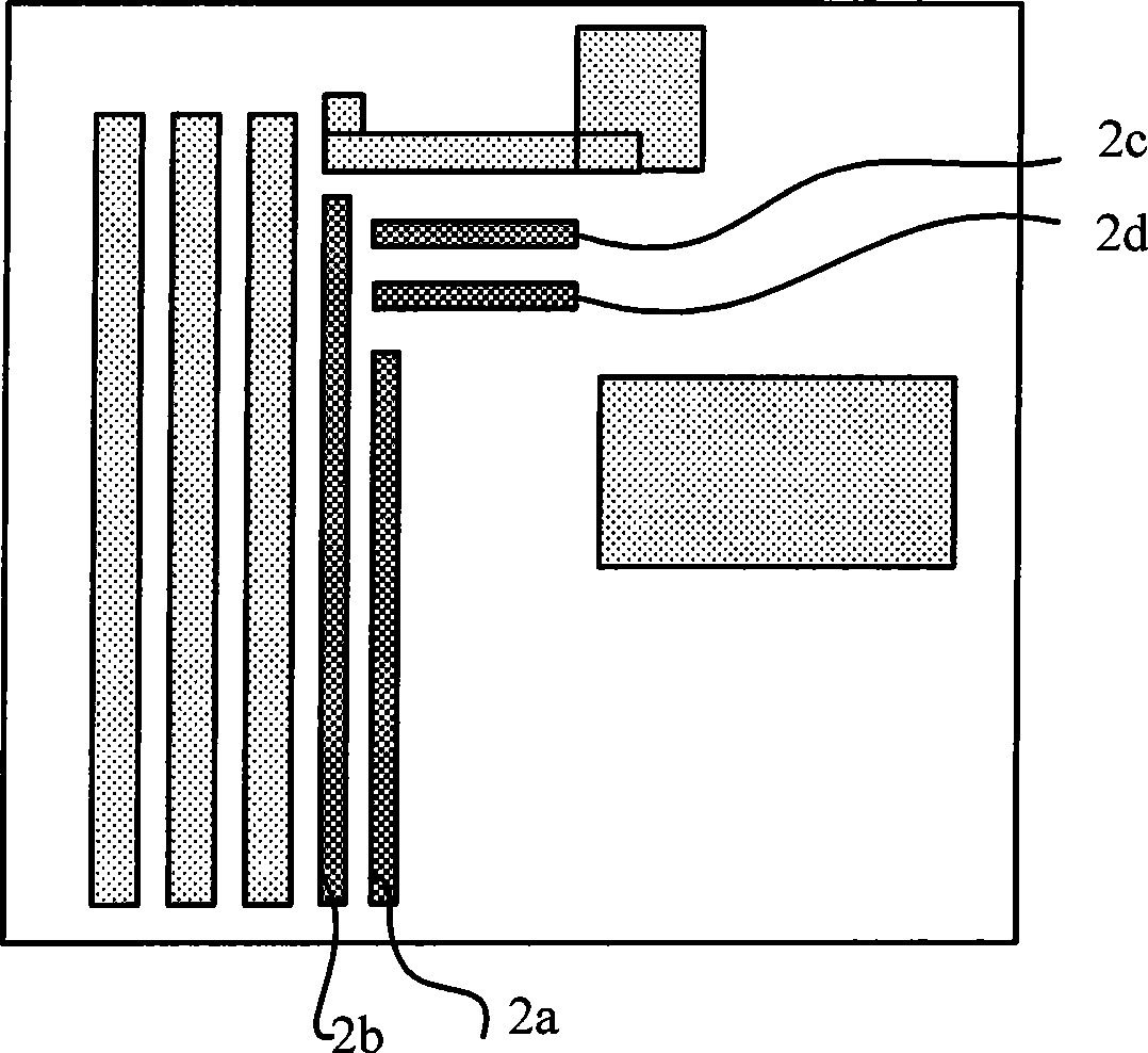
[0014] When the main pattern is placed on the lithography isolation or semi-isolation photomask, it is necessary to insert scattering bars in the main pattern to improve the resolution of the lithography pattern. see figure 1 , figure 1 The filling pattern in 1 is the same as the main pattern of the photomask template. Taking the main pattern shape of the photomask as an example, the method of generating the scattering strips is described. First, insert the scattering bars with preset parameter values ​​in the main graphics of the photomask template, such as figure 2 The scattering bars shown in 2a, 2b, 2c and 2d, from figure 2 It can be seen in 2c and 2d that the scatter strips bridge with the scatter strip 2a. Next, the influencing factors of the bridged scattering bars 2c, 2d and 2a are determined, and the influencing factors of the scattering bars are sorted by size. The influence factors of the scattering bars 2c, 2d and 2a are determined by calculating the normaliz...


PUM


Abstract

The invention provides a generation method for scattering bars. The method is mainly applied to the improvement of the photolithographic quality of a separated or semi-separated pattern. The method comprises the following steps: 1, inserting the scattering bars with preset parameter values in the main patterns of a photo masking plate; 2, judging effect factors of the bridged scattering bars in the inserted scattering bars, and sorting the effect factors according to the size; 3, correcting the bridged scattering bar with the minimum effect factor till the scattering bar is not connected with other scattering bars with larger effect factors; and 4, further detecting whether the bridged scattering bars exist in the rest scattering bars, if yes, returning to step 3, and if no, stopping the correction of the scattering bars. The generation method for the scattering bars can effectively solve the problem that: according to the prior generation method for the scattering bars, important scattering bars are randomly shortened or removed, thereby affecting the photolithographic quality.

Description

technical field [0001] The invention relates to resolution enhancing technology in semiconductor lithography, in particular to a method for generating scattering bars for enhancing resolution. Background technique [0002] In the semiconductor lithography process of technology nodes of 0.13um or lower, resolution enhancement technology (resolution enhancement technology) is widely used. Scatter bar (scatter bar) is a very common resolution enhancement (RET) technology. Its main principle is to adjust the light intensity distribution density of the pattern by inserting sub-precision auxiliary patterns into the main feature of the photomask. . In this way, the process window of the photolithography process can be effectively enlarged. [0003] Usually, scattering bars are inserted in the main pattern of the isolated or semi-isolated photomask to expand the process window of the photolithography process. The current method for generating scatter bars is to generate inserted ...

Claims


Application Information

Patent Timeline
Patent Type & Authority Applications(China)
IPC IPC(8): G03F1/14G03F1/00G03F1/72
Inventor 刘娟
Owner SEMICON MFG INT (SHANGHAI) CORP
Why Eureka
Try Eureka