Method for improving RH vacuum furnace bottom groove life

A technology of bottom tank and vacuum furnace, which is applied in the field of RH vacuum refining equipment, can solve the problems of low service life and frequent maintenance of the bottom tank of RH vacuum furnace, and achieve the effect of increasing service life, increasing average service life and obvious effect

Inactive Publication Date: 2009-06-17
ANGANG STEEL CO LTD
View PDF0 Cites 11 Cited by
  • Summary
  • Abstract
  • Description
  • Claims
  • Application Information

AI Technical Summary

Problems solved by technology

[0003] In order to solve the problems of low service life and frequent maintenance of the bottom groove of the RH vacuum furnace in the prior art, the present invention provides a method that can effectively improve the life of the bottom groove of the RH vacuum furnace

Method used


Image

  • Method for improving RH vacuum furnace bottom groove life

Examples


Embodiment Construction

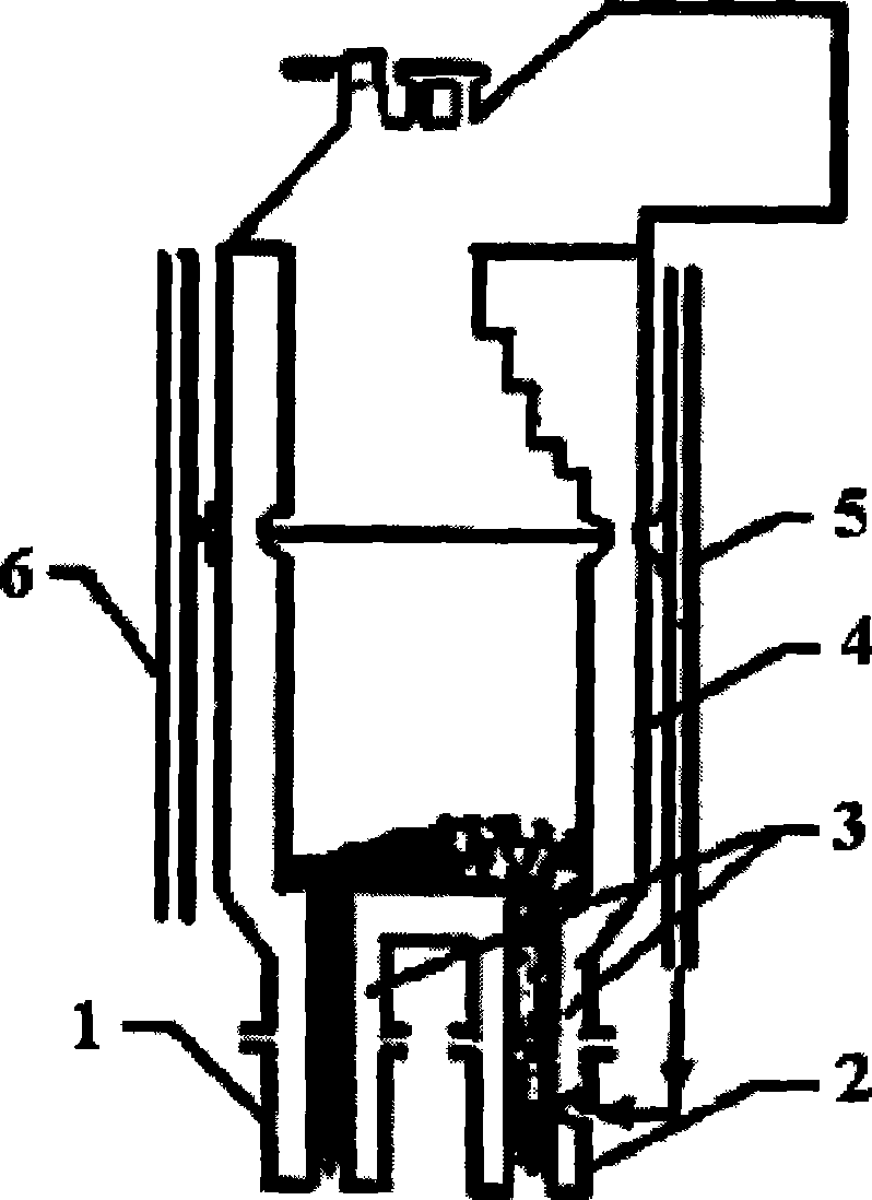
[0009] The present invention will be further described below through embodiments with reference to the accompanying drawings.

[0010] Firstly, an argon blowing system 6 is added on the opposite side of the argon blowing system 5 on one side of the vacuum chamber 4 of the RH vacuum furnace, that is, on the side of the downcomer 1 of the dip tube. When the dipping tube has reached the end of its service life and the vacuum chamber 4 needs to be off-line for maintenance, remove the dipping tube ascending pipe 2 and descending pipe 1, and after knotting the circulating pipe 3, install the descending pipe 1 at the position of the original ascending pipe 2 , Install the rising pipe 2 at the position of the original descending pipe 1, and exchange the positions of the two. Then connect the argon gas in the riser 2 to the newly added argon blowing system 6, and after the replacement, it can continue to be used. Adopting this method can effectively improve the service life of the bot...


PUM


Abstract

The invention provides a method for prolonging the service life of a bottom tank of an RH vacuum furnace. The method is characterized in that: the opposite side of an argon blowing system of a vacuum chamber is added with an argon blowing system, the position of a riser and the position of a downcomer are exchanged when a new varnished tube is mounted, and an argon tube of the riser is connected to the newly added argon blowing system. The method helps realize the alternate use of a circulation tube at the ascending side and a circulation tube at the descending side of the bottom tank by exchanging the position of the riser and the position of the downcomer, thus avoiding that the circulation tube at one side always bears the intense scouring of the raising steel flow, effectively prolonging the service life of the circulation tubes, and further prolonging the service life of the bottom tank. The method has obvious effect and can help improve the average service life of the bottom tank by more than one fold.

Description

technical field [0001] The invention belongs to the technical field of steelmaking equipment, and in particular relates to RH vacuum refining equipment. Background technique [0002] The circulation pipe at the bottom groove of the RH vacuum furnace is a part with relatively harsh smelting conditions. It is not only corroded by steel slag, but also has the circulation scour of high-temperature molten steel and the scour of oxygen stream, which makes it frequently maintained and has a short service life. It is effective for the RH vacuum furnace. Operational impact is huge. Moreover, the design of the RH bottom tank cannot replace the circulating pipe alone, and the entire bottom tank is often replaced only because of the damage of the circulating pipe, resulting in a lot of waste of refractory materials. Therefore, improving the service life of the bottom tank has become an urgent problem to be solved. Contents of the invention [0003] In order to solve the problems of ...

Claims


Application Information

Patent Timeline
Patent Type & Authority Applications(China)
IPC IPC(8): C21C7/10
Inventor 姚伟智赵爱英许海亮孟宪敏刘敏
Owner ANGANG STEEL CO LTD
Why Eureka
Try Eureka