Damping and sealing tube joint

A sealing tube and sealing ring technology, applied in the field of pipe joints, can solve problems such as unsatisfactory sealing effect, many parts, troublesome installation, etc., and achieve the effects of increasing compression resistance, convenient opening/closing, and increasing service life

Inactive Publication Date: 2009-06-17
苏州捷英特管道技术有限公司
View PDF0 Cites 7 Cited by
  • Summary
  • Abstract
  • Description
  • Claims
  • Application Information

AI Technical Summary

Problems solved by technology

The disadvantage of this kind of pipe joint is that there are many parts, and the installation is more troublesome, and the sealing effect is not ideal

Method used


Image

  • Damping and sealing tube joint
  • Damping and sealing tube joint
  • Damping and sealing tube joint

Examples


Embodiment Construction

[0024] The present invention In order to better understand the present invention, the present invention will be further described in detail below in conjunction with the accompanying drawings. The pipe joint in the preferred embodiment of the present invention includes a connecting device and a sealing device, a toothed entrainment belt, a triangular steel belt, and a stainless steel wire ring.

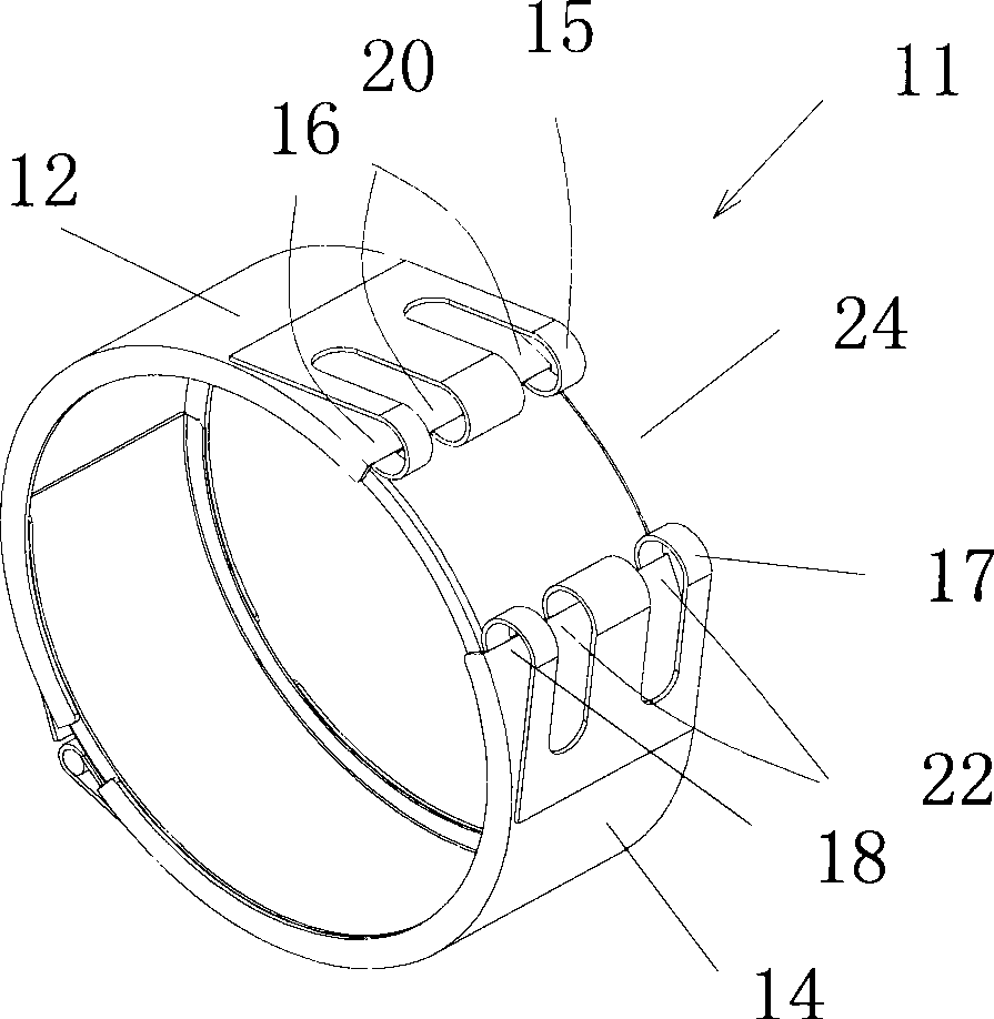
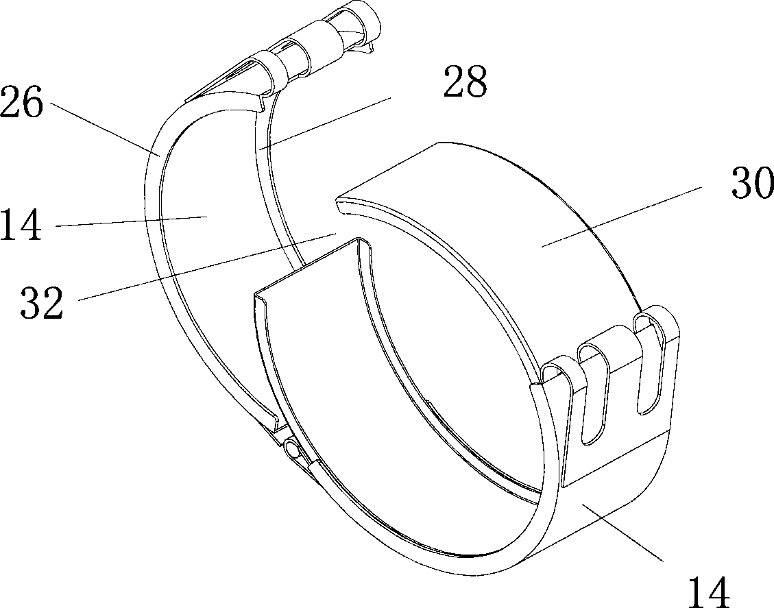
[0025] see figure 1 and figure 2 As shown, the connection device 10 of the preferred embodiment of the present invention includes an open annular shell 11 with a certain axial width and a clamping device 13 for clamping the shell 11 (such as Figure 6 shown). The shell 11 is formed by hinge connection of a first arc-shaped shell 12 and a second arc-shaped shell 14 . The free ends of the first housing 12 and the second housing 14 are respectively bent outwards to form lugs 15, 17 with axial through holes 16, 18, and lugs 15, 17 are also provided with axially spaced holes. A plural...


PUM


Abstract

The invention provides a damping sealing pipe connector which belongs to the technical field of industry. The invention comprises a connection device and a sealing device, wherein the connection device comprises an opening annular outer case formed by connecting two arc-shaped case body hinges, and a clamping device for claming the open end of the outer case. The pipe connector of the invention adopts the opening annular outer case with the structure connected by two arc-shaped case body hinges, and can be conveniently opened and closed. The gap in the opening of the outer case can be adjusted at random in certain amplitude, which is convenient for the built-in installation of a sealing ring.

Description

technical field [0001] The invention relates to a pipe connection device, in particular to a pipe joint capable of shock absorption and sealing. Background technique [0002] In pipeline construction, pipeline connection is a very common application requirement. At present, pipe joints are widely used for pipe connection. [0003] The pipe joints in the prior art generally adopt a monolithic structure, including an open annular shell, a sealing ring built in the shell, the outer wall of the sealing ring is close to the inner wall of the shell, and a fastening device is located on the shell for fastening the shell. When the fastening device is tightened, the gap at the opening of the shell shrinks, so that the shell forms a radially inward clamping force on the sealing ring, so that the shell is tightened, and then the inner wall of the sealing ring shrinks to clamp and place it The outer wall of the inner pipe achieves a seal. However, the pipe joint housing only has an o...

Claims


Application Information

Patent Timeline
Patent Type & Authority Applications(China)
IPC IPC(8): F16L17/02
Inventor 凌坚昌
Owner 苏州捷英特管道技术有限公司
Why Eureka
Try Eureka