
Pretightening sealing ball valve device

A technology for sealing ball valves and ball valves, applied in valve devices, valve operation/release devices, cocks including cut-off devices, etc., can solve problems such as low success rate of ball valves

Inactive Publication Date: 2009-12-16
SHENGLI PETROLEUM ADMINISTRATION BUREAU DRILLING TECH ACAD SINOPEC
View PDF0 Cites 13 Cited by
  • Summary
  • Abstract
  • Description
  • Claims
  • Application Information

AI Technical Summary

Problems solved by technology

There is no ball valve preload function in the ball valve structure, so the success rate of ball valve closing and pressure maintaining is low, which cannot meet the actual needs

Method used


Image

  • Pretightening sealing ball valve device

Examples


Embodiment Construction

[0008] The present invention will be further described now in conjunction with the accompanying drawings of the description.

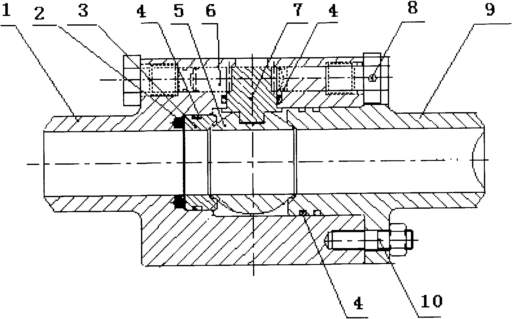
[0009] When adopting the present invention to carry out the coring operation, the ball valve lower body 1 is connected with the ball valve upper body 9 through the fastening screw 10, and the ball valve upper body 9 and the ball valve lower body 1 are provided with a round hole for assembling the rack 6 and the gear 7, and the spring 2 Installed under the lower body 1 of the ball valve, the sealing metal body 3 and the ball valve 5 are installed in the lower body 1 of the ball valve, on the top of the spring 2, the surface of the sealing metal body (3) and the ball valve (5) are covered with wear-reducing materials, and the gear 7 passes through the teeth Embedded and connected to the ball valve 5, the rack 6 and the gear 7 are meshed through the teeth, and the rack 6 is fixed on the upper body 9 of the ball valve and the lower body 1 of the ball valve ...


PUM


Abstract

The invention relates to a pretightening sealing ball valve device which comprises a ball valve lower body, a spring, a sealing metal body, a sealing ring, a ball valve, a rack, a gear, hydraulic transfer tubes, a ball valve upper body and tightening screw nails. The ball valve lower body is connected with the ball valve upper body through the tightening screw nails; the ball valve upper body and the ball valve lower body are provided with circular holes for assembling the rack and the gear; the spring is arranged below the ball valve lower body; the sealing metal body and the ball valve are arranged inside the ball valve lower body and positioned above the spring; carbon materials are laid on the surfaces of the sealing metal body and the ball valve; the gear is connected with the ball valve through interlocking teeth; the rack is meshed with the gear through teeth, and fixed on the ball valve upper body and the ball valve lower body through the hydraulic transfer tubes at two ends; and when the ball valve is required to work, the hydraulic transfer tubes transfer liquid so as to exert a force on the rack, so that the rack rotates the gear, and the gear drives the ball valve to rotate to lead the ball valve to be in a closing mode. As the spring is arranged below the ball valve, the ball valve has self-tightness, thereby ensuring the tightness of the ball valve to be more reliable, and improving the feasibility of the operation.

Description

technical field [0001] The invention relates to a natural gas hydrate coring operation device, which belongs to a special operation for new energy exploration and development. Background technique [0002] Carrying out the ball valve that coring operation is used at present is that ball valve is closed by external force by the moment arm that is connected with ball valve outside ball valve. If this structure is to ensure that the ball valve is closed, it is necessary to arrange a movable outer cylinder outside the ball valve body. When the ball valve needs to be closed, it first requires that the outer cylinder and the ball valve body have a differential, and the ball valve is closed by the weight of the outer cylinder. There is no ball valve preload function in the ball valve structure, so the success rate of ball valve closing and pressure maintaining is low, which cannot meet the requirements of actual needs. Contents of the invention [0003] The technical problem to ...

Claims


Application Information

Patent Timeline
IPC IPC(8): F16K5/06F16K5/14F16K5/08F16K27/06F16K31/12
Inventor 许俊良赵宏宇姜正陆薄万顺朱杰然
Owner SHENGLI PETROLEUM ADMINISTRATION BUREAU DRILLING TECH ACAD SINOPEC
Learn More