Air filtration for nuclear reactor habitability area

A technology of nuclear reactors and air filtration devices, applied in the direction of renewing breathing air devices, applications, nuclear engineering, etc.

Inactive Publication Date: 2009-06-17
GE HITACHI NUCLEAR ENERGY AMERICAS
View PDF4 Cites 4 Cited by
  • Summary
  • Abstract
  • Description
  • Claims
  • Application Information

AI Technical Summary

Problems solved by technology

During a radiological and/or poisoning incident, such detours of piping from outside the CRHA may be problematic

Method used


Image

  • Air filtration for nuclear reactor habitability area
  • Air filtration for nuclear reactor habitability area
  • Air filtration for nuclear reactor habitability area

Examples


Embodiment Construction

[0070] The following description is merely exemplary in nature and is not intended to limit the invention, application or uses. Throughout the specification, like reference numerals will be used to refer to like elements.

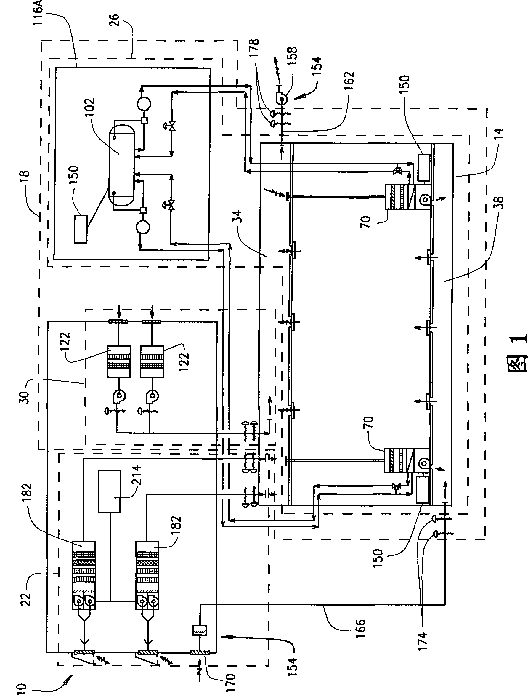
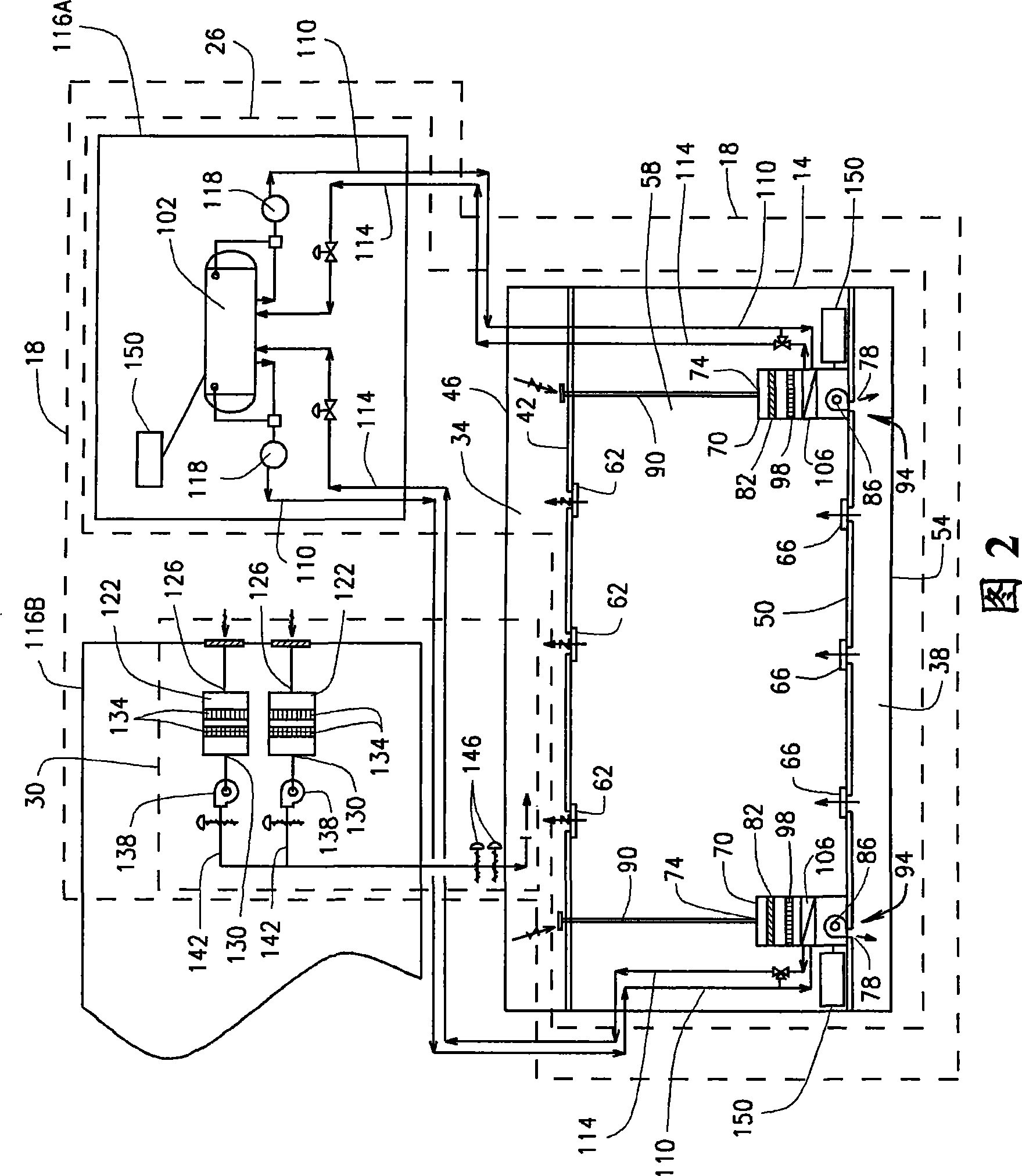
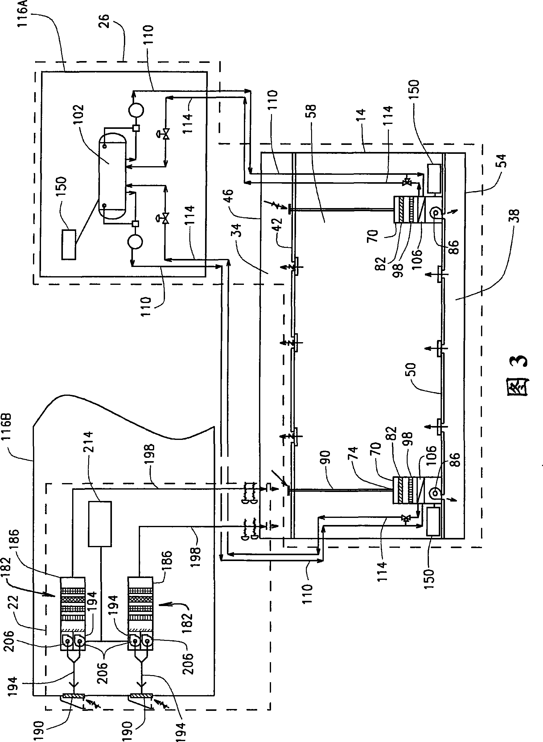
[0071] 1 is a block diagram of an air filtration and conditioning (AFC) system 10 for use in a habitability zone 14 of a nuclear reactor facility, according to various embodiments of the present disclosure. Habitability zone 14 may be any area, room or building of a nuclear reactor facility, such as a nuclear reactor power plant, configured to be occupied by humans. For example, in various embodiments, the habitability area 14 may be a control room of a nuclear reactor power plant constructed and equipped to be occupied by various plant personnel to control the operation of the plant. AFC system 10 is configured and operable to generate airflow within habitability zone 14 that provides safe breathable air to occupants of habitability zone 14 . More specif...


PUM


Abstract

A system for providing air substantially free from radioactive and toxic contaminates to a nuclear reactor habitability area is provided. The system can include at least one emergency air filtration unit structured and operable to provide air free from radioactive and toxic contaminates to the habitability area. The system can additionally include at least one stored energy power source structured and operable to provide operating power to each emergency air filtration unit.

Description

technical field [0001] The present invention relates to systems and methods for providing filtered air to habitability regions of nuclear reactor facilities. Background technique [0002] The statements in this section merely provide background information related to the present disclosure and may not necessarily constitute prior art. [0003] Nuclear power plants require emergency systems that provide "fresh air" to the plant's Control Room Habitability Area (CRHA) in case of radiological and / or poisoning incidents, i.e. accidental release of radioactive and / or toxic pollutants, gases or smoke or leak. Compressed air storage systems are usually employed in such situations for the emergency habitability of the main control room to provide clean and safe air, ie air free of radioactive and toxic contaminants. Such known compressed air storage systems require the storage of large compressed air tanks and the installation of associated lines, piping, valves, regulators, instr...

Claims


Application Information

Patent Timeline
IPC IPC(8): F24F3/16F24F8/108F24F8/158
CPCA62B11/00G21F9/02F24F3/1603F24F3/161F24F3/167F24F8/10F24F8/108F24F8/158
Inventor R·G·小奥斯丁M·萨尔瓦
Owner GE HITACHI NUCLEAR ENERGY AMERICAS
Why Eureka
Try Eureka