Sliding mechanism

A technology of sliding mechanism and sliding plate, which is applied in the direction of support structure installation, telephone communication, electrical components, etc. It can solve the problems of complex cost of sliding mechanism, large swing space, and limitation of miniaturization of sliding mechanism

Inactive Publication Date: 2009-06-17
HONG FU JIN PRECISION IND (SHENZHEN) CO LTD +1
View PDF0 Cites 3 Cited by
  • Summary
  • Abstract
  • Description
  • Claims
  • Application Information

AI Technical Summary

Problems solved by technology

First of all, the spring 67 of the sliding mechanism is completely exposed outside the main body plate 50 and the sliding plate 60. During use, it is easy to be stuck by other parts of the portable electronic device, so that the sliding plate 60 cannot continue to slide, which brings inconvenience to the use. inconvenient
[0007] Secondly, since the guide rods 65 connected to the main body plate 50 and the sliding plate 60 require a certain swing space, and the sliding mechanism also has two guide rods 65, resulting in a larger swing space required, so the sliding mechanism is limited. At the same time, the main body plate 50 and the sliding plate 60 are located on the same side of the connecting mechanisms such as the guide rod 65 and the spring 67, so the width of the main body plate 50 must be greater than the sliding plate 60 to install the hinge shaft 62, which also limits the sliding mechanism. miniaturization
[0008] Again, the sliding mechanism requires two sets of hinge shafts 62, guides 52, guide rods 65 and springs 67 so that the main body plate 50 and the sliding plate 60 maintain balance during the relative sliding process, resulting in a more complicated sliding mechanism and higher cost

Method used


Image

  • Sliding mechanism
  • Sliding mechanism
  • Sliding mechanism

Examples


Embodiment Construction

[0018] The sliding mechanism of the present invention will be further described in detail with reference to the accompanying drawings and embodiments.

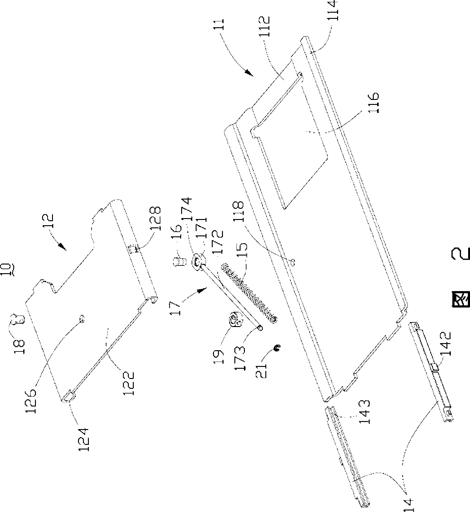
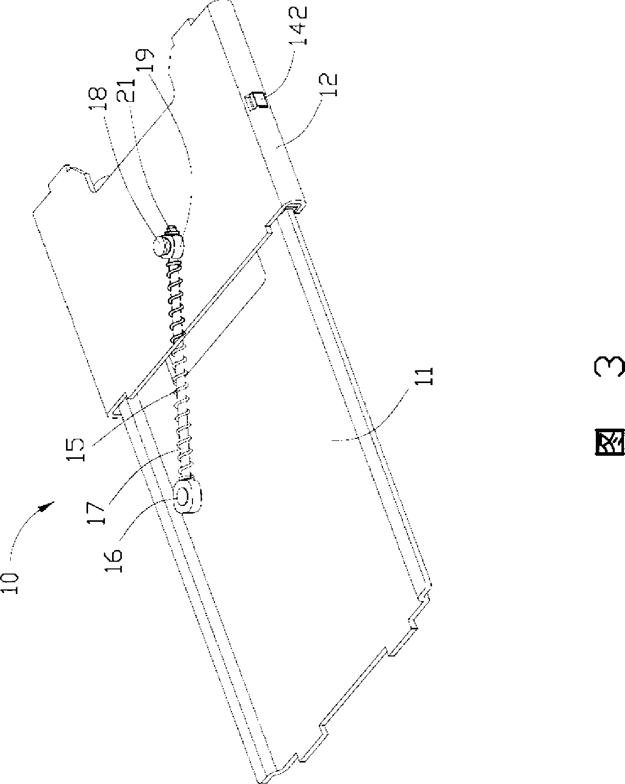
[0019] Referring to FIG. 2 , the sliding mechanism 10 of the preferred embodiment 1 of the present invention includes a backboard 11 , a sliding board 12 , two backboard slide rails 14 , a spring 15 and a sliding rod 17 .

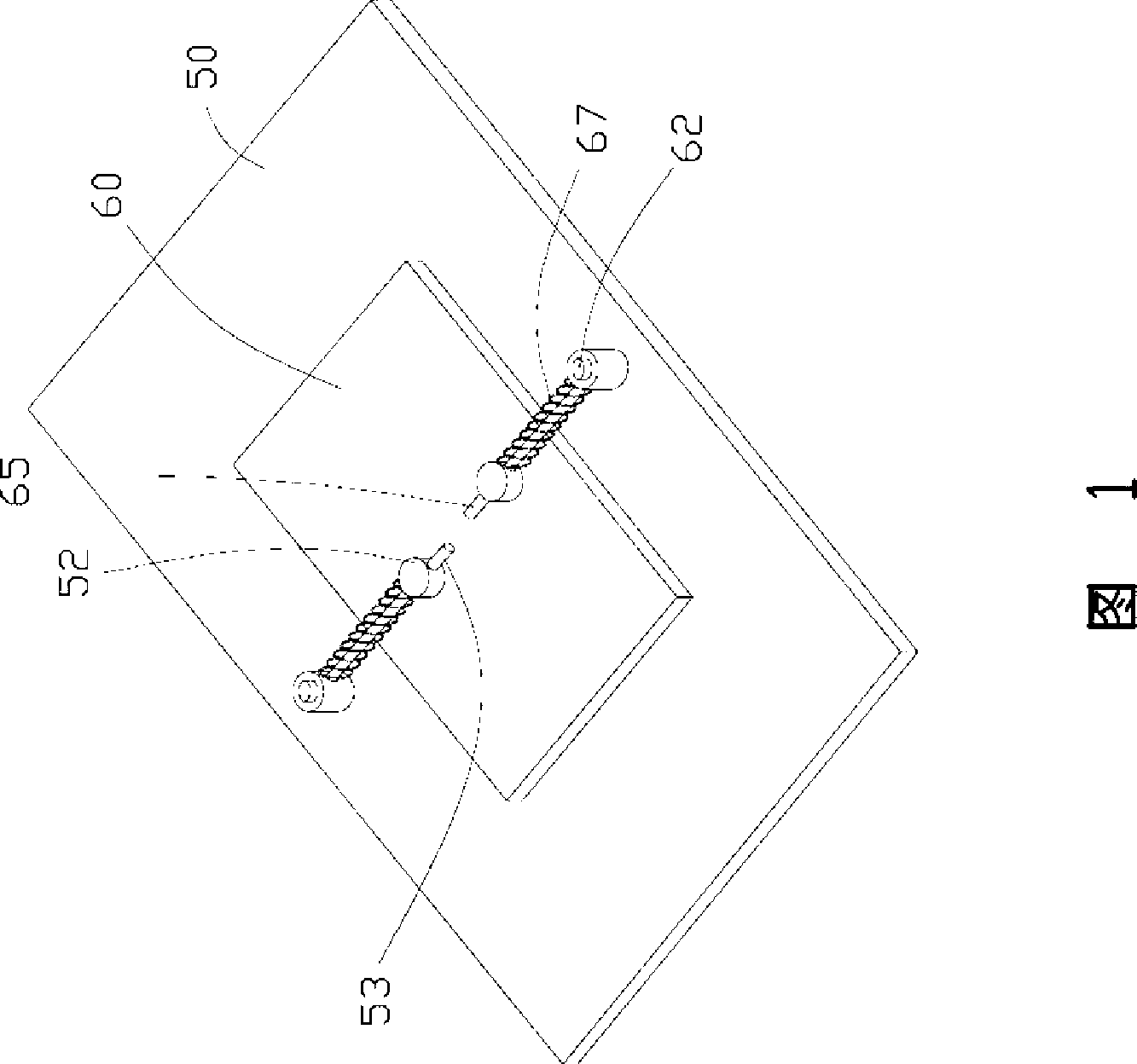
[0020] The back plate 11 is generally a rectangular plate, which includes a bottom plate 112 . Two opposite sides of the bottom plate 112 are slightly bent toward the same side of the bottom plate 112 , thereby forming two matching flanges 114 . There is also a square hole 116 and a pin hole 118 on the bottom plate 112 , the pin hole 118 is close to a mating flange 114 of the back plate 11 , and the square hole 116 is provided to facilitate the assembly of the sliding mechanism 10 .

[0021] The sliding plate 12 is substantially a rectangular plate, which includes a base portion 122 , two opposite sides of...


PUM


Abstract

The invention discloses a slide mechanism, which comprises a back board, a slide plate which is matched with the back board, and can slide relative to the back board, and a connecting assembly, wherein the connecting assembly comprises an elastic piece and a slide bar, the slide bar is connected to the back board and the slide plate, two ends of the slide bar rotate relative to the back board and the slide board respectively, the elastic piece is sleeved on the slide bar, the connecting assembly uses the elasticity of the elastic piece to push the slide plate and the back board to relatively slide, and the connecting assembly is clamped between the back board and the slide plate. The spring of the slide mechanism of the invention can not easily lock other parts of portable electronic devices, thereby not causing inconvenient operation.

Description

technical field [0001] The invention relates to a sliding mechanism, in particular to a sliding mechanism applied to portable electronic devices. Background technique [0002] In recent years, portable electronic devices have become more and more popular, and sliding portable electronic devices are favored and loved by consumers. [0003] Current slide-type portable electronic devices are mainly classified into three categories. One type adopts a manual sliding mechanism, that is, the user moves the sliding cover manually through the whole process. There is also a semi-automatic sliding mechanism. The user only needs to push the sliding cover to a certain distance, and the sliding cover will automatically move and locate to a fully closed state or a fully open state. The other type adopts a fully automatic sliding mechanism, and the user can realize the automatic movement of the sliding mechanism in the whole process by pressing a button. The manual sliding mechanism is i...

Claims


Application Information

Patent Timeline
Patent Type & Authority Applications(China)
IPC IPC(8): H05K7/14
CPCH04M1/0237
Inventor 李坚王金鑫
Owner HONG FU JIN PRECISION IND (SHENZHEN) CO LTD
Why Eureka
Try Eureka