Protective sleeve

A technology for protecting sleeves and protecting units, applied in the direction of insulators, etc., can solve the problems of contact with the tube body and arc, and achieve the effect of preventing excessive bending, preventing damage, and reducing the probability of arc phenomenon.

Inactive Publication Date: 2011-12-14
AU OPTRONICS CORP
View PDF0 Cites 0 Cited by
  • Summary
  • Abstract
  • Description
  • Claims
  • Application Information

AI Technical Summary

Problems solved by technology

However, since the protective frames 120 of the protective sleeve 100 are arranged along the extension direction D1 of the pipe body 110, the iron pieces 50 interlaced with the protective sleeve 100 are easy to penetrate into the gap G between two adjacent protective frames 120, and even touch to pipe body 110
In this way, the distance between the wire rod in the pipe body 110 and the iron piece 50 will be too short, thus arc phenomenon will occur

Method used


Image

  • Protective sleeve
  • Protective sleeve
  • Protective sleeve

Examples


Embodiment Construction

[0049] In order to have a clearer understanding of the technical features, purposes and effects of the present invention, the specific implementation manners of the present invention will now be described with reference to the accompanying drawings.

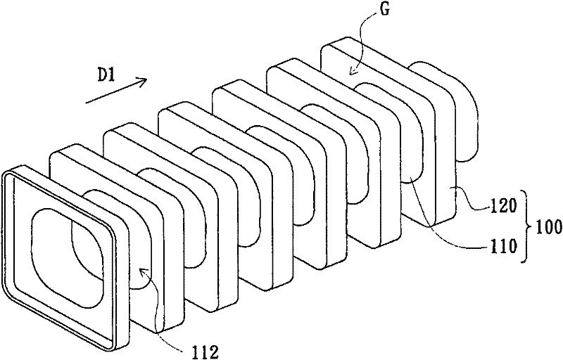
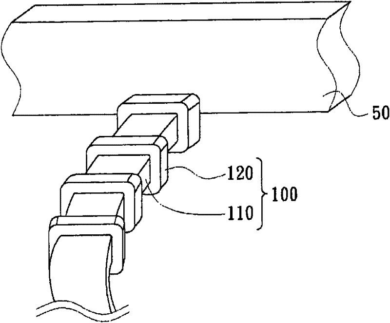
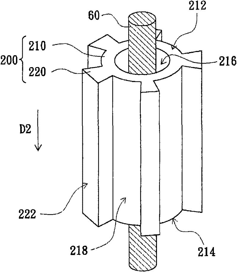
[0050] image 3 is a three-dimensional schematic diagram of a protective sleeve according to an embodiment of the present invention, and Figure 4 Is iron parts touching image 3 Schematic diagram of the protective sleeve. Please refer to image 3 and Figure 4 , the protective sleeve 200 of this embodiment is suitable for protecting the wire 60 . The protection sleeve 200 includes a tube body 210 and a plurality of protection units 220 . The tube body 210 has a first end 212 , a second end 214 and a through hole 216 extending from the first end 212 to the second end 214 . The wire 60 passes through the through hole 216 , and part of the wire 60 is located in the through hole 216 . The protection units 220 protrude from th...


PUM


Abstract

The invention discloses a protective sleeve suitable for protecting wires. The protective sleeve includes a tube body and a plurality of protection units. The tube body has a first end, a second end and a through hole extending from the first end to the second end. , the wire passes through the through hole, and part of the wire is located in the through hole, the protection unit protrudes from the outer surface of the pipe body, each protection unit extends along a predetermined direction, and the protection units are arranged at intervals on the outer surface of the pipe body, The above-mentioned predetermined direction is from the first end to the second end. In addition, the material of the pipe body and the protection unit is insulating material, and the protection unit is used to maintain an appropriate distance between the wire rod and the iron piece in the pipe body. Preventing arc phenomenon; wherein, each protection unit has a top surface away from the outer surface, and the top surface is a plane.

Description

technical field [0001] The invention relates to a protective sleeve, in particular to a wire protection sleeve. Background technique [0002] In electronic products, the wire used to transmit high-voltage electricity is covered with a protective sleeve to prevent the wire from contacting other iron parts in the electronic product. However, if the distance between the protective sleeve and the iron piece is too close, arcing is likely to occur, especially at the bend of the wire. The occurrence of the arc phenomenon can easily cause the protective sleeve and the wire to burn black, thereby affecting the safety and reliability of the electronic product. Therefore, it is necessary to take effective precautions against this arc phenomenon. [0003] figure 1 It is a three-dimensional schematic diagram of a known protective sleeve. Please refer to figure 1 , the known protective sleeve 100 includes a tubular body 110 and a plurality of protective frames 120 extending outward ...

Claims


Application Information

Patent Timeline
Patent Type & Authority Patents(China)
IPC IPC(8): H01B17/58
Inventor 杨明奕郑美俊杨顺益陈信志
Owner AU OPTRONICS CORP
Why Eureka
Try Eureka