

Ceramic antenna structure
A technology of ceramic antenna and carrier, applied in the direction of radiating element structure, antenna support/installation device, etc., can solve the problems of separation of ceramic antenna and circuit board, inability of electronic devices to receive or transmit signals, inability to achieve efficiency, etc.
- Summary
- Abstract
- Description
- Claims
- Application Information
AI Technical Summary
Problems solved by technology
Method used
Image

Examples
Embodiment Construction
[0050] The detailed description and technical content of the present invention are described below with accompanying drawings. However, the attached drawings are provided for reference and illustration only, and are not intended to limit the present invention.
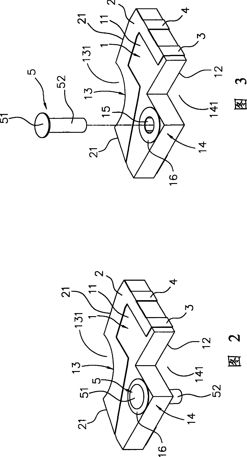
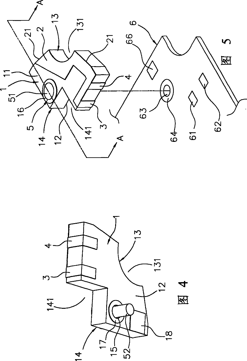
[0051] see Figure 2 to Figure 4 , is a schematic diagram of the appearance, decomposition and bottom view of the ceramic antenna structure in the present invention. The ceramic antenna structure in the present invention includes a carrier 1 , a radiation component 2 , a ground component 3 , an input component 4 and a fixing pin 5 .
[0052] The carrier 1 is made of a ceramic material with a dielectric coefficient of 19.4, has a first side 11 and a second side 12 on it, and a first end 13 and a second end 14 connected to the first and second sides 11, 12, The first end 13 has an arc-shaped notch 131 , and the second end 14 has an L-shaped notch 141 . In addition, the carrier 1 is provided with a through hole 15 adjac...
PUM
 Abstract
Description
Claims
Application Information