A High Gain Patch Antenna with Broadband and Filtering Characteristics

A filter characteristic, patch antenna technology, applied in the direction of antenna grounding switch structure connection, radiation element structure, etc., can solve the problem of high antenna profile, achieve the effect of improving the working bandwidth and increasing the gain

Active Publication Date: 2020-05-05
SHENZHEN UNIV
View PDF7 Cites 0 Cited by
  • Summary
  • Abstract
  • Description
  • Claims
  • Application Information

AI Technical Summary

Problems solved by technology

However, the use of Γ-type coupled feeders makes the profile of the antenna very high

Method used


Image

  • A High Gain Patch Antenna with Broadband and Filtering Characteristics
  • A High Gain Patch Antenna with Broadband and Filtering Characteristics
  • A High Gain Patch Antenna with Broadband and Filtering Characteristics

Examples


Embodiment Construction
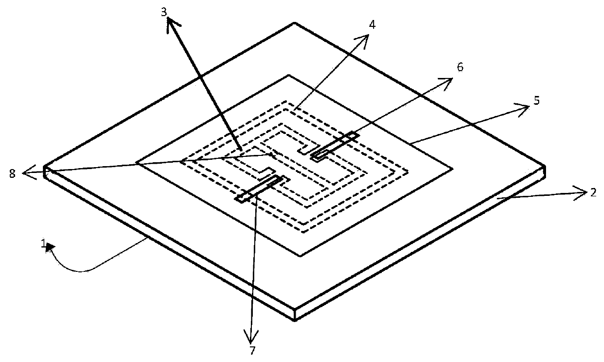
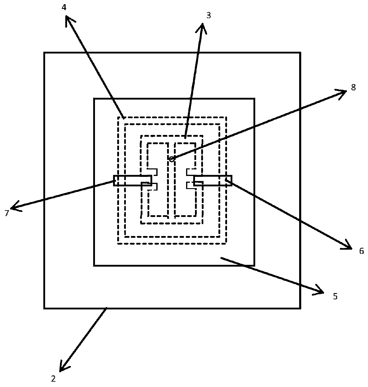
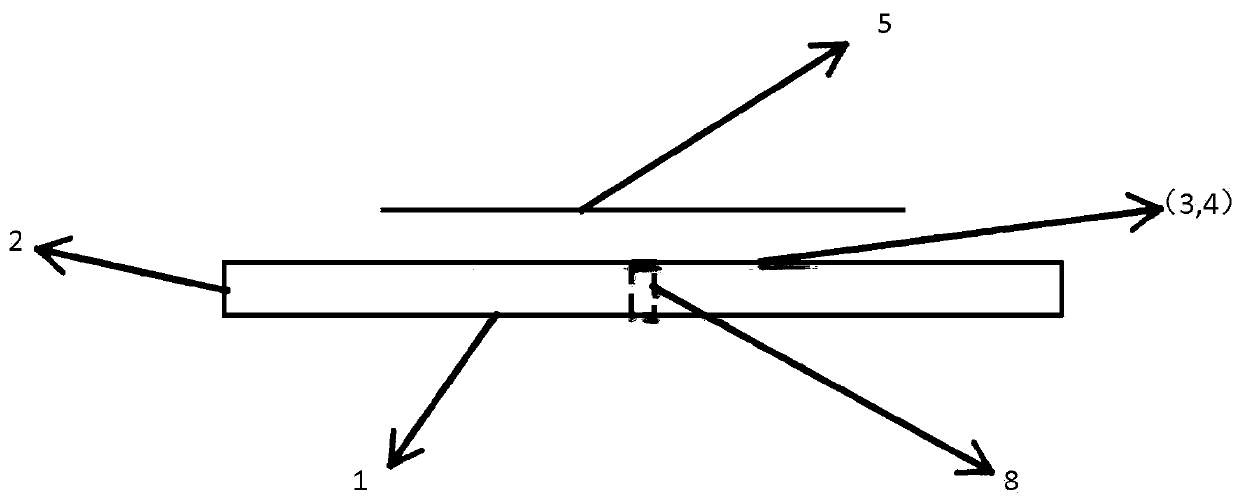
[0017] The most critical idea of ​​the present invention is to open two grooves on the radiation patch, and the direction of the grooves is perpendicular to the rectangular microstrip of the first resonant unit. The radiation patch is coupled with the first resonant unit and the second resonant unit. By making slots on the radiation patch, the current distribution and field distribution of the antenna in the high-order resonance mode are changed, and the gain of the patch antenna is greatly improved by suppressing the side lobe of the E plane and reducing the beam width of the H plane, and at the same time Multiple resonant modes are introduced through multiple resonant unit coupling feeds, thereby improving the working bandwidth of the antenna.

[0018] In order to describe the technical content, structural features, achieved goals and effects of the present invention in detail, the following will be described in detail in conjunction with the embodiments and accompanying dra...


PUM


Abstract

The invention provides a high-gain patch antenna with wideband and filter characteristics, comprising a dielectric substrate, a metal base plate, a radiation patch, a first resonant unit, a second resonant unit and a feeder. A metal bottom plate is connected to one side of that dielectric substrate, and two resonance units are connected to the other side of the dielectric substrate. The radiationpatch is arranged above the two resonance units, and the first resonance unit and the second resonance unit are concentric structure. The radiation patch is provided with two grooves, and the groove direction is perpendicular to the direction of the rectangular microstrip constituting the first resonant unit. The outer contour of the radiation patch is rectangular, and its side length is larger than half of the free space wavelength in the working band. The layers that make up the antenna are thin so that the profile of the antenna is low. By slotting on the radiation patch to change the current distribution and field distribution of the antenna in high-order resonant mode, the gain of the antenna is greatly improved by lowering the sidelobe of the E-plane and reducing the beam width of the H-plane. The bandwidth of the antenna is increased by introducing multiple resonant modes into the coupling feed of multiple resonant elements.

Description

technical field [0001] The invention relates to a patch antenna, in particular to a high-gain patch antenna with broadband and filter characteristics. Background technique [0002] In recent years, with the rapid development of wireless communication and increasingly complex application scenarios, the bandwidth and other performance requirements of antennas in wireless communication systems are getting higher and higher. [0003] First of all, due to the needs of the application environment, many wireless communication components must be embedded or integrated into a small communication device, which requires miniaturization of these components; at the same time, from the perspective of market products, Practical antennas should also have low profile, light weight, and easy fabrication. Secondly, the signal coverage and distance of the communication system are affected by the antenna gain. In order to combat transmission loss, the antenna is required to have a higher gain i...

Claims


Application Information

Patent Timeline
Patent Type & Authority Patents(China)
IPC IPC(8): H01Q1/36H01Q1/38H01Q1/50
CPCH01Q1/36H01Q1/38H01Q1/50
Inventor 洪凯东张晓黄冠龙袁涛吴琼森祝雷
Owner SHENZHEN UNIV
Why Eureka
Try Eureka