omnidirectional ceiling antenna

A technology for ceiling-mounted antennas and cylindrical rings, applied in antennas, resonant antennas, antenna components, etc., can solve the problem of omnidirectional ceiling-mounted antennas not considering the downward aggregation of higher frequency signals such as LTE/4G, and the radiation intensity under the antenna High frequency, LTE/4G and other higher frequency signal coverage efficiency is low, to achieve the effect of uniform indoor signal coverage, reduce electromagnetic radiation, and expand effective coverage

Active Publication Date: 2016-09-21
CHINA UNITED NETWORK COMM GRP CO LTD
View PDF4 Cites 0 Cited by
  • Summary
  • Abstract
  • Description
  • Claims
  • Application Information

AI Technical Summary

Problems solved by technology

[0004] However, with the deployment of higher frequency networks such as LTE / 4G, the omnidirectional ceiling antenna improved by the above technology does not consider the problem of downward aggregation of higher frequency signals such as LTE / 4G, and the maximum gain direction for frequencies above 2500MHz is about 60°. The gain attenuation in the 85° direction reaches about 2dB, and the downward signal aggregation is still very obvious, so that the coverage efficiency of LTE / 4G and other higher frequency signals is still low, and the radiation intensity under the antenna is still high

Method used


Image

  • omnidirectional ceiling antenna
  • omnidirectional ceiling antenna
  • omnidirectional ceiling antenna

Examples


Embodiment Construction

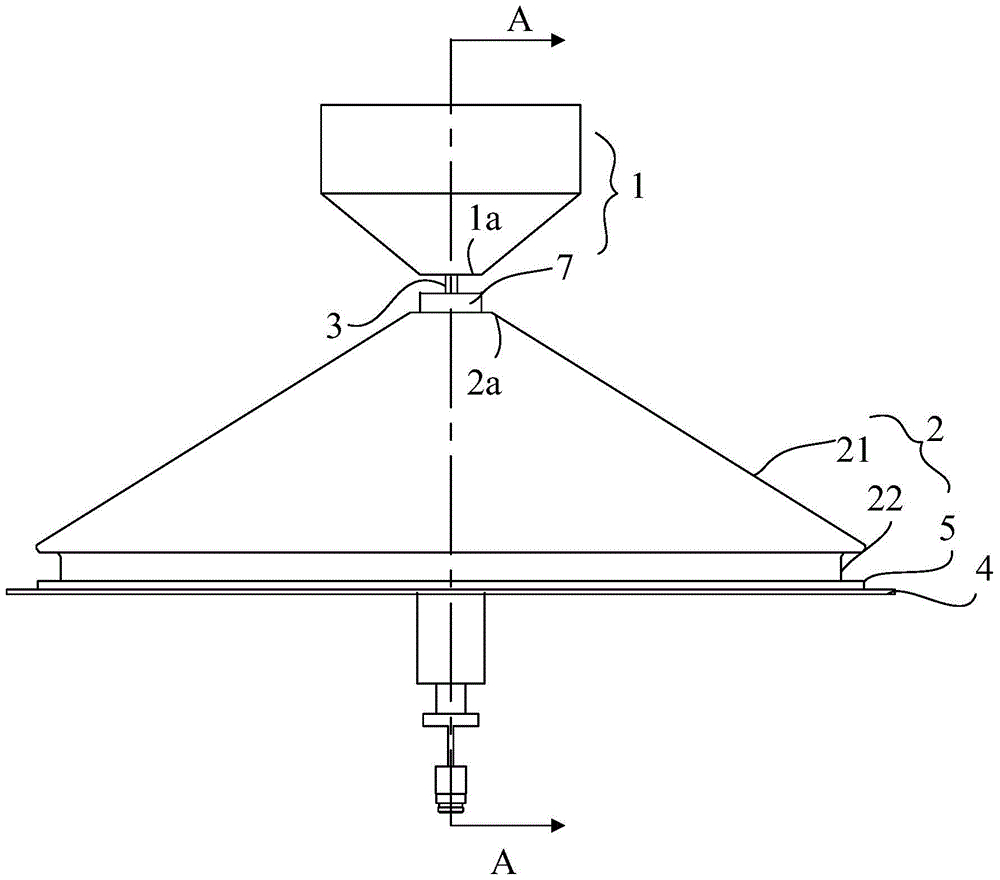
[0021] figure 1 It is a schematic diagram of the structure of an embodiment of the omnidirectional ceiling antenna of the present invention, that is, the front view, such as figure 1 As shown, the omnidirectional ceiling antenna of this embodiment includes: a cone-shaped radiation oscillator 1, a cone-shaped reflector 2, a plate-shaped bottom plate 4, a hollow tubular terminal 7 and a feeder cable 3; The tip 2a of the reflector 2 faces the tip 1a of the radiating oscillator 1, the center of the tip 1a of the radiating oscillator 1 is connected to the inner conductor of the feeder cable 3, the center hole of the tip 2a of the reflector 2 fixes the terminal 7, and It is connected to the outer conductor of the feeder cable 3 through the terminal post 7 . The antenna also includes: an insulating dielectric ring 5 . The reflector 2 includes a first hollow cone 21 and a first cylindrical ring 22, the flared end of the first hollow cone 21 is connected to the first cylindrical ring...


PUM


Abstract

The present invention provides an omnidirectional ceiling antenna, which includes a cone-shaped radiating oscillator, a cone-shaped reflector, a disc-shaped bottom plate, and an insulating dielectric ring; wherein the reflector includes a first hollow cone and a first cylindrical ring , the flared end of the first hollow cone is connected to the first cylindrical ring, and the outer diameter of the first cylindrical ring is smaller than the outer diameter of the flared end of the first hollow cone; a second cylindrical ring is arranged on the bottom plate, and the second cylindrical ring is connected to the first cylindrical ring. The cylindrical rings are socketed to form a space-isolated coupling structure; the insulating dielectric ring is arranged between the second cylindrical ring and the first cylindrical ring to realize isolation and support and fixation between the reflector and the bottom plate. The invention solves the problem that the high-frequency signal of the ultra-broadband indoor omnidirectional antenna gathers downward, not only expands the effective coverage of the high-frequency signal, makes the indoor signal distribution more uniform, but also effectively reduces the electromagnetic radiation intensity under the antenna, ensuring indoor Safety in the electromagnetic environment.

Description

technical field [0001] The invention relates to mobile communication technology, in particular to an omnidirectional ceiling antenna. Background technique [0002] Mobile communication indoor omnidirectional ceiling antennas are widely used in indoor distribution systems. They are the main type of antennas used for indoor wireless signal coverage. Their performance and quality directly affect the quality of indoor wireless communication and the investment efficiency of indoor distribution systems. Omnidirectional ceiling antennas generally use the half-wave vibrator principle, using a conical vibrator plus reflector structure. The conical vibrator can widen the impedance broadband of the antenna. The existing omnidirectional ceiling antenna in China usually connects the impedance matching line (piece) between the radiating vibrator and the reflective floor to reduce the volume and further expand the bandwidth of the low-end frequency to meet the requirements of 806 The requ...

Claims


Application Information

Patent Timeline
Patent Type & Authority Patents(China)
IPC IPC(8): H01Q1/12H01Q15/16
CPCH01Q9/28H01Q1/007H01Q1/2291H01Q5/25H01Q19/10
Inventor 黄晓明刘新良陈新明傅强莫俊彬邓安民
Owner CHINA UNITED NETWORK COMM GRP CO LTD
Why Eureka
Try Eureka