A wide-band helical antenna and its design method

A helical antenna and broadband technology, applied in the field of broadband helical antenna and its design, can solve the problem that the helical antenna cannot meet the requirements of multi-frequency and broadband, and achieve the effect of wide bandwidth

Active Publication Date: 2022-05-06
QINGDAO UNIV
View PDF0 Cites 0 Cited by
  • Summary
  • Abstract
  • Description
  • Claims
  • Application Information

AI Technical Summary

Problems solved by technology

[0005] In the embodiment of the present application, a wide-band helical antenna and its design method are provided to help solve the problem that the helical antenna in the prior art cannot meet the multi-frequency and broadband requirements

Method used


Image

  • A wide-band helical antenna and its design method
  • A wide-band helical antenna and its design method
  • A wide-band helical antenna and its design method

Examples


Embodiment 1

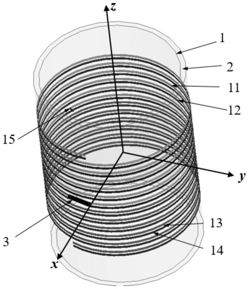
[0049] In this embodiment, Figure 1a The specific parameters of the shown broadband helical antenna are as follows. For the convenience of description, the broadband helical antenna with the following parameters is named ANT1C41.

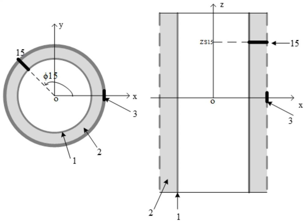
[0050]The specific parameters of ANT1C41 are: the inner radius of the hollow cylinder is a=6.5mm, the outer radius is b=7mm, and the height h is less than 25mm. ANT1C41 includes four helical metal wires, each of which starts at the middle part of the cylinder, wherein the first helical metal wire 11 and the second helical metal wire 12 are wound side by side on the upper half of the hollow cylinder; the third The spiral metal wire 13 and the fourth spiral metal wire 14 are wound side by side on the lower half of the hollow cylinder, and the end of each spiral metal wire is open. The feeding points 3 are respectively connected to the starting ends of the four spiral metal wires. The number of turns of each spiral metal wire is the same as 6. The A...

Embodiment 2

[0106] In this embodiment, Figure 1a The specific parameters of the shown broadband helical antenna are as follows. For the convenience of description, the broadband helical antenna with the following parameters is named ANT2C6.

[0107] The specific parameters of ANT2C6 are: it contains four spiral metal wires and a short circuit point, and the number of spiral metal coils can be different.

[0108] Figure 10 A schematic structural diagram of the antenna ANT2C6 provided in the embodiment of the present application, in Figure 23 The number of turns of the first spiral metal wire 21 is n1=12, the number of turns of the second spiral wire 22 is n2=6, the number of turns of the third spiral wire 23 is n3=12, and the number of turns of the fourth spiral wire 24 For n4=8, the helix angle of the short-circuit point is φ15=240°.

[0109] Table 4 is a comparison table of resonant frequency and bandwidth under different circumstances of the antenna ANT2C6 helical number of turns p...

Embodiment 3

[0121] In this embodiment, Figure 1a The specific parameters of the shown broadband helical antenna are as follows. For the convenience of description, the broadband helical antenna with the following parameters is named ANT3536.

[0122] Figure 14 A schematic diagram of the structure of the antenna ANT3536 provided in this embodiment of the application, the specific parameters of the ANT3536 are: including two short-circuit points and four spiral metal wires, wherein the two short-circuit points are the first short-circuit point 35 and the second short-circuit point 36 respectively, The four spirals have the same number of turns, n=7.

[0123] In order to study the working principle of ANT3536, three reference antennas are given in the embodiment of this application, namely ANT35 (only the first short-circuit point 35 has no second short-circuit point 36), ANT36 (only the second short-circuit point 36 has no first short-circuit point) 35), ANT30 (without short-circuit poin...


PUM


Abstract

The embodiment of the present application discloses a broadband helical antenna and its design method. The antenna includes a hollow cylinder and a helical metal wire. The inner layer of the hollow cylinder is a metal ground, and the outer layer of the hollow cylinder is The magnetic material, the spiral metal wire is wound on the outside of the magnetic material, and the spiral metal wire is also provided with a feed point and a short-circuit point, and the short-circuit point is used to conduct the spiral metal wire and the metal ground. The broadband helical antenna provided by the embodiment of the present application adds a short-circuit point, connects the helical metal wire and the metal ground, can change the current distribution, form a new current path to form a new radiation oscillator, and excite multiple resonances in the 10-80MHz frequency band mode to form a multi-band, broadband antenna with a wide bandwidth. The antenna provided by the embodiment of the present application further includes a radio frequency switch, which is used to adjust the disconnection or connection status of the short-circuit metal sheet and the disconnection or connection status of the spiral metal wire, thereby adjusting the resonant frequency.

Description

technical field [0001] The present application relates to the field of antenna technology, and in particular, to a broadband helical antenna and a design method thereof. Background technique [0002] Antenna is a component used in radio equipment to transmit or receive electromagnetic waves. It converts guided waves propagating on transmission lines into electromagnetic waves propagating in free space, or vice versa. It is widely used in radio communications, radio, and television. , radar, navigation, electronic countermeasures, remote sensing, radio astronomy and other engineering systems. [0003] In many wireless communication systems, antennas are required to be small, multi-frequency, and broadband, such as antennas in capsule endoscopes. In the prior art, in order to reduce the size of the antenna in the capsule endoscope, the antenna is usually made into a helical structure. Since the main part of the capsule endoscope is cylindrical, the helical antenna can be woun...

Claims


Application Information

Patent Timeline
Patent Type & Authority Patents(China)
IPC IPC(8): H01Q1/36H01Q1/48H01Q1/50H01Q9/27
CPCH01Q1/36H01Q1/48H01Q1/50H01Q9/27
Inventor 宗卫华刘路路李洪飞王建青李山东
Owner QINGDAO UNIV
Why Eureka
Try Eureka