Triangular track structure of two-sided terry circular knitting machine

A technology of circular knitting machine and double-faced wool, which is applied to circular knitting machines with individual moving needles, weft knitting, textiles and papermaking, etc. It can solve problems such as broken yarns, burst holes, and failure to improve fabric quality. , to avoid yarn breakage and blast holes, and to achieve the same effect of pile length

Inactive Publication Date: 2009-07-15
洪荣豪
View PDF0 Cites 5 Cited by
  • Summary
  • Abstract
  • Description
  • Claims
  • Application Information

AI Technical Summary

Problems solved by technology

[0002] The structure of a general double-sided terry circular knitting machine is usually to install two different shapes of raw gram in the raw gram groove of the needle cylinder, and to install the knitting needle in the knitting needle groove of the needle cylinder, and to install the knitting needle in the needle cylinder. The upper and lower sides of the outer surface are respectively equipped with triangular tracks, and the legs of the green sheet and the stitches of the knitting needles are respectively placed in the upper and lower triangular tracks, and driven by the rotation of the needle cylinder and the track of the triangular tracks. The actions of the squeegee and the knitting needle, and cooperate with the yarn of the yarn feeder to carry out the knitting needle and hook yarn to weave the cloth. The stroke design of the needle for special movements usually can only weave a double-sided terry cloth surface, and the length of the terry loops on the surface cannot be controlled to be consistent, resulting in uneven lengths of the terry loops on the surface, and even yarn breakage And the phenomenon of blasting holes, so the quality of the fabric cannot be improved

Method used


Image

  • Triangular track structure of two-sided terry circular knitting machine
  • Triangular track structure of two-sided terry circular knitting machine
  • Triangular track structure of two-sided terry circular knitting machine

Examples


Embodiment Construction

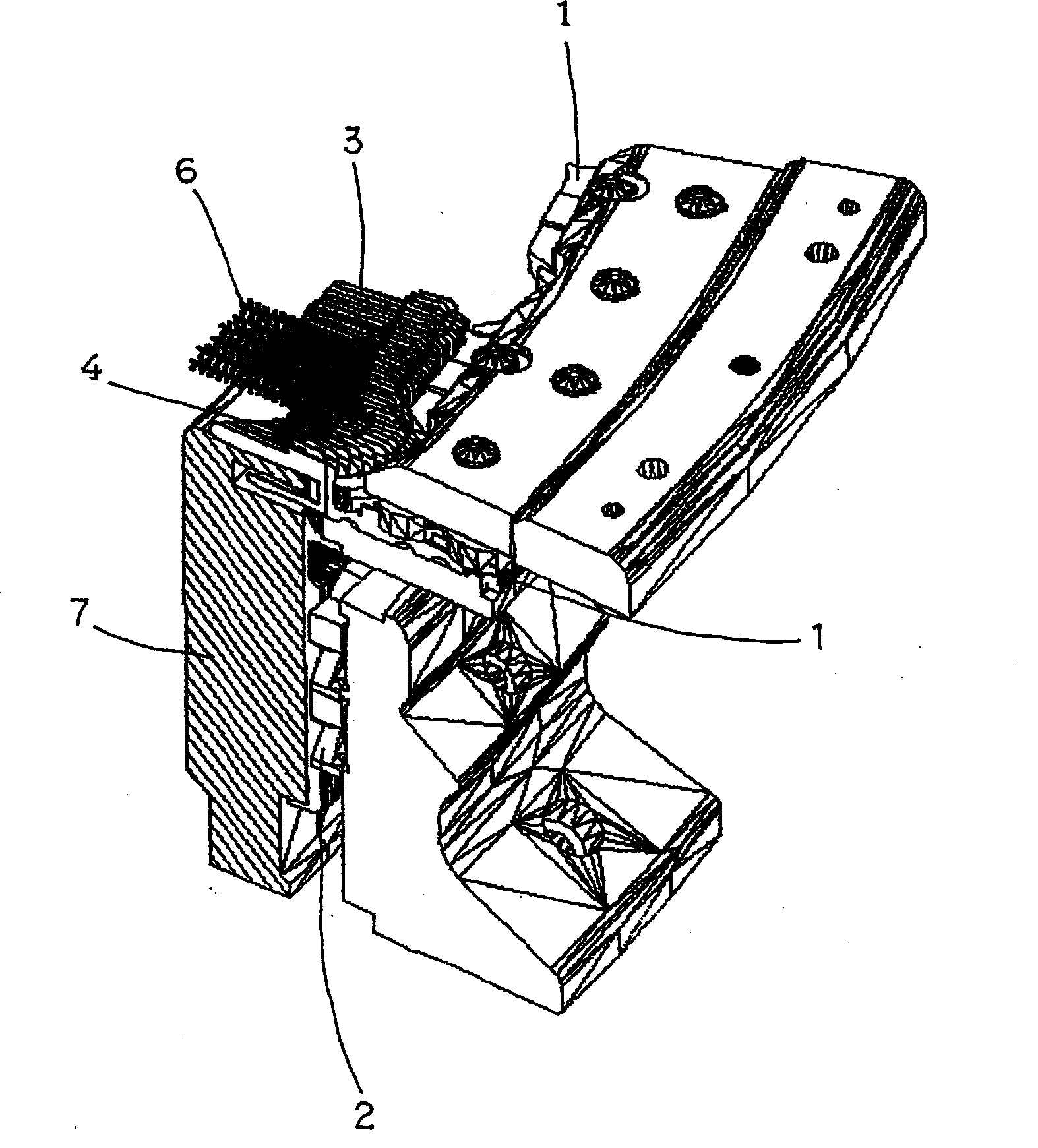
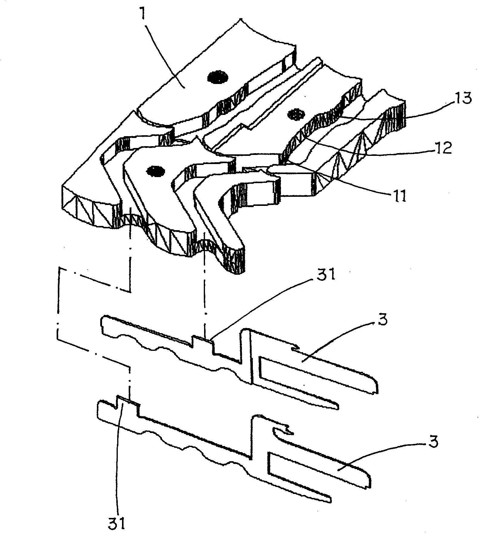
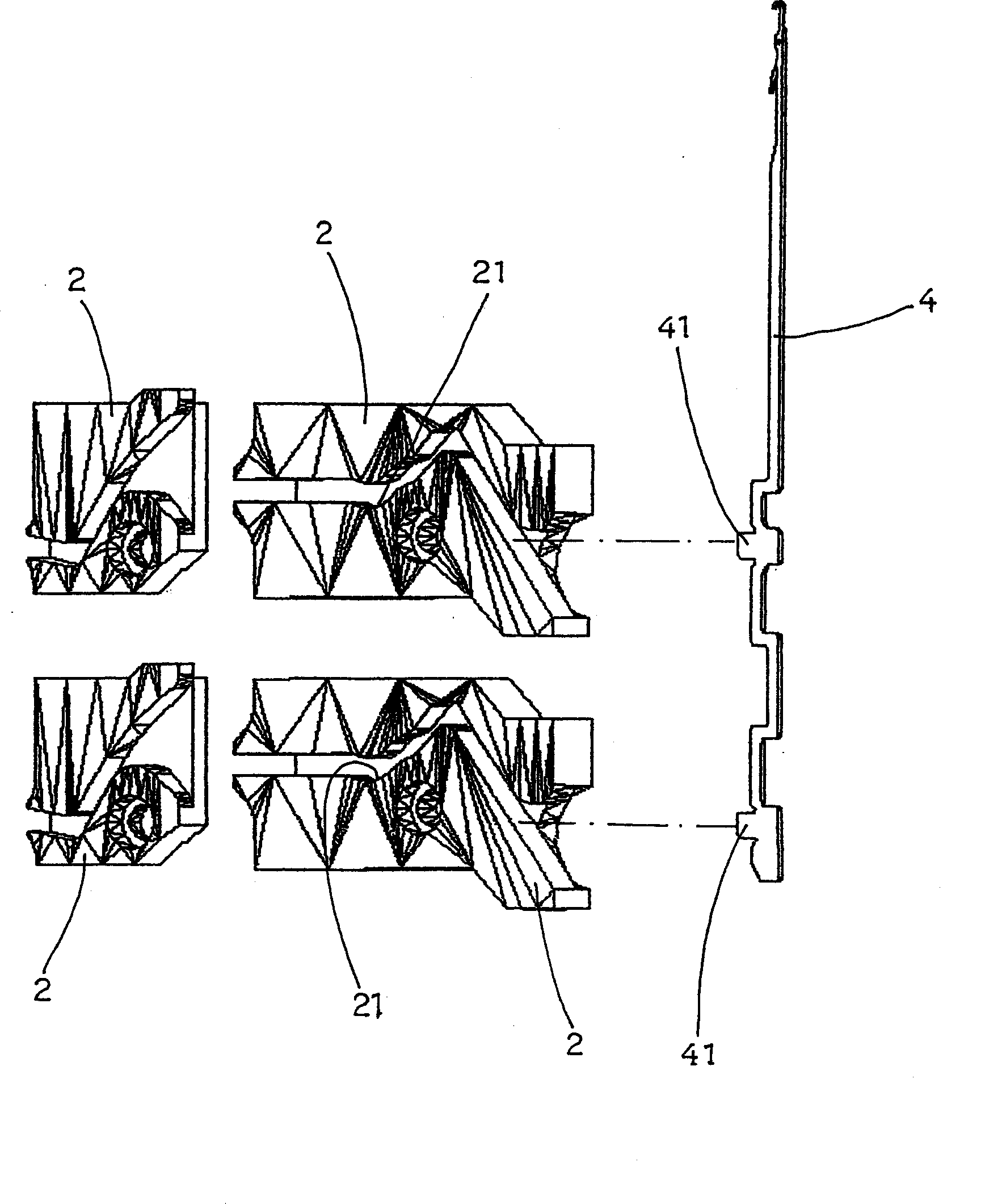
[0021] see Figure 1~3 , the accessories of the triangular track structure of the double-sided circular terry knitting machine of the present invention are the same as those of the generally known double-sided circular terry knitting machine. Sheet 3, and knitting needle 4 is installed in the knitting needle groove of needle cylinder 7, and upper and lower triangular tracks 1, 2 are respectively established on the outside of needle cylinder 7, and the sheet feet 31 and 2 of raw gram sheet 3 are The stitches 41 of the knitting needle 4 are respectively placed in the upper and lower triangular tracks 1 and 2, and the raw sheet 3 and the knitting needle 4 are driven by the rotation of the needle cylinder 7 and the tracks of the upper and lower triangular tracks 1 and 2 action, and cooperate with the yarn of the yarn feeder 5 to carry out the knitting needle hook yarn weaving cloth, and the present invention is mainly to drive the yarn eating section of the upper triangular track ...


PUM


Abstract

The invention discloses a triangle track structure of a double-side terry circular knitting machine. The structure comprises a sinker and a knitting needle which are arranged in a needle cylinder sinker slot and a knitting slot, an upper triangle track and a lower triangle track which drive the sinker and the knitting needle to act, the front section of a yarn taking section of the upper triangle track which drives the sinker to act is a convex slot area which causes the sinker to extend slightly forward, a concave slot area capable of causing the sinker to slightly retract is connected at the rear section of the yarn taking section, and the convex slot area capable of causing the sinker to extend a bit forwards is connected at the rear section of the yarn taking section; and the front end of a half needle section of the lower triangle track which drives the kitting needle to act is provided with the concave slot area which causes the knitting needle to slightly decline and recover. The triangle track structure causes the terry at the face side of knitted fabrics to have the same length and be neat, prevents broken yarn and blow holes, and can cause the knitting to be labor saving and smooth while acting.

Description

technical field [0001] The invention relates to a triangular track structure of a double-sided pile circular knitting machine. Background technique [0002] The structure of a general double-sided terry circular knitting machine is usually to install two different shapes of raw gram in the raw gram groove of the needle cylinder, and to install the knitting needle in the knitting needle groove of the needle cylinder, and to install the knitting needle in the needle cylinder. The upper and lower sides of the outer surface are respectively equipped with triangular tracks, and the legs of the raw gram sheet and the stitches of the knitting needles are respectively placed in the upper and lower triangular tracks, and driven by the rotation of the cylinder and the track of the triangular tracks. The actions of the squeegee and the knitting needles, and cooperate with the yarn of the yarn feeder to carry out the knitting needle hook yarn to weave the cloth. The stroke design of th...

Claims


Application Information

Patent Timeline
Patent Type & Authority Applications(China)
IPC IPC(8): D04B15/32D04B9/10
Inventor 洪荣豪
Owner 洪荣豪
Why Eureka
Try Eureka