Planting base, planting body, planting base unit, planting system, and planting method

A base plate and plant body technology, applied in planting base plates, planting bodies, planting base plate groups, planting systems and planting fields, can solve the problem that water is easily affected by wind, it is difficult to use heavy greening systems, it takes time and Labor and other issues

A base plate and plant body technology, applied in planting base plates, planting bodies, planting base plate groups, planting systems and planting fields, can solve the problem that water is easily affected by wind, it is difficult to use heavy greening systems, it takes time and Labor and other issues

CN101489374AInactive Publication Date: 2009-07-22TOYOTA JIDOSHA KK

Image

  • Planting base, planting body, planting base unit, planting system, and planting method
  • Planting base, planting body, planting base unit, planting system, and planting method
  • Planting base, planting body, planting base unit, planting system, and planting method

Examples


Embodiment Construction

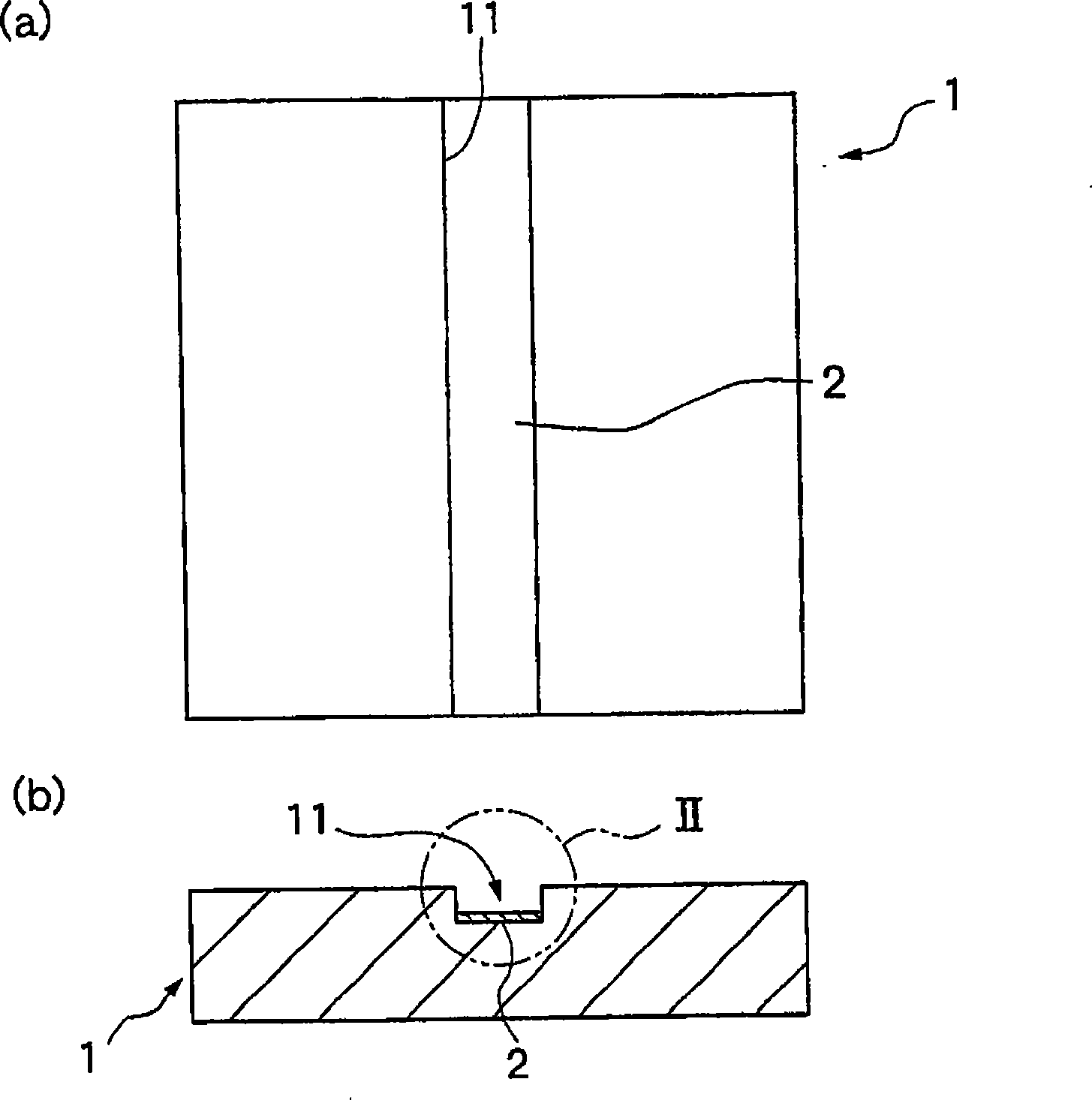
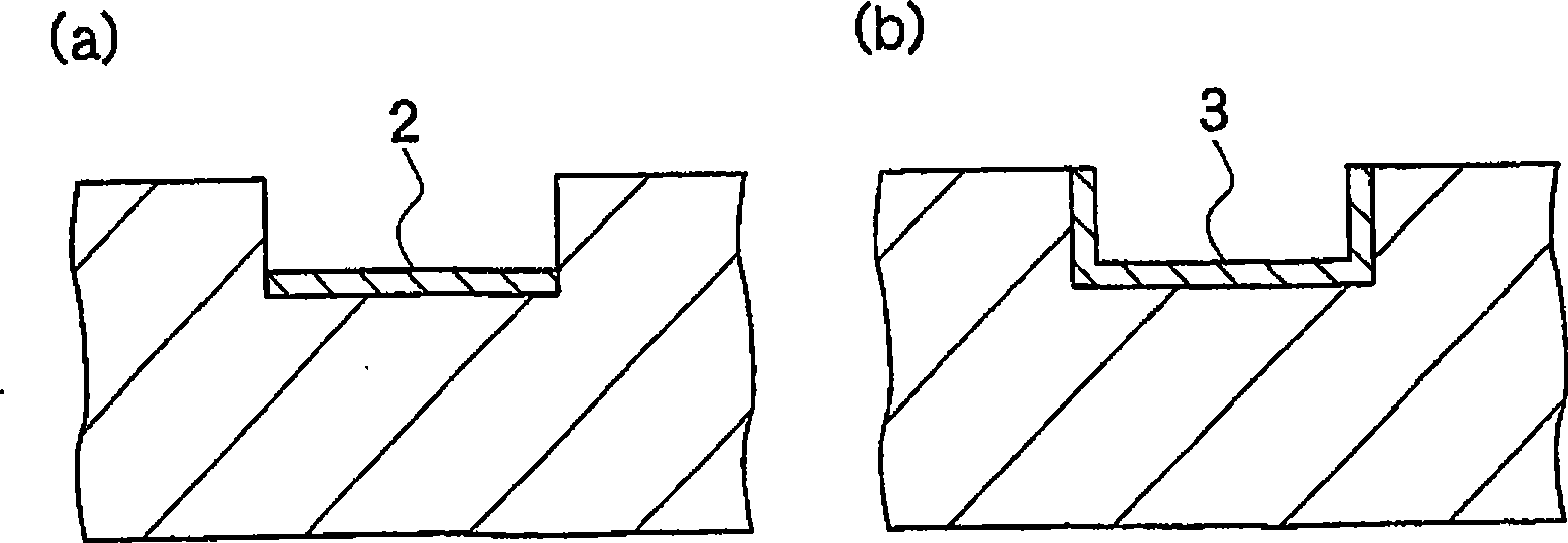
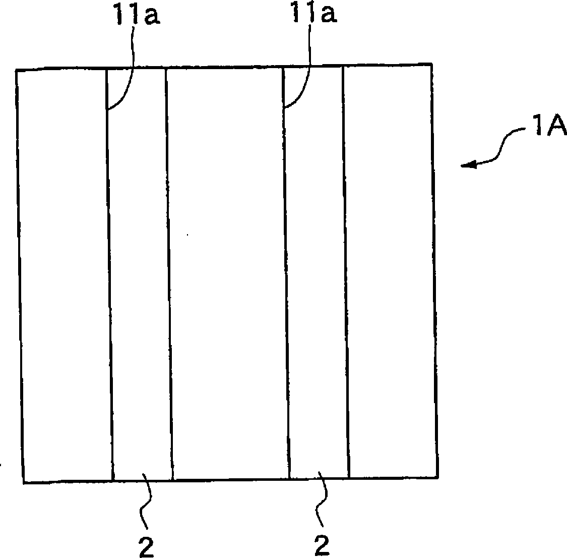
[0048] Embodiments of the present invention will be described below with reference to the drawings. figure 1 It is a figure showing one embodiment of the planting base of the present invention, figure 1 a is the floor plan, figure 1 b is a cross-sectional view. figure 2 a. figure 2 b respectively represent figure 1 Enlarged view of part II of b, Figure 3-6 Each shows a plan view of another embodiment of the planting base of the present invention. Figure 7 It is a figure which shows one embodiment of the planting body of this invention, Figure 7 a is the floor plan, Figure 7 b is a cross-sectional view. Figure 8 It is a figure which shows one embodiment of the planting system of this invention, Figure 8 a is the floor plan, Figure 8 bCross-section diagram. Figures 9 to 11 It is figure explaining planting method sequentially. Figure 12 is a diagram explaining the outline of the experiment, Figure 12 a shows the floor plan, Figure 12 b shows a sectional ...


PUM


Abstract

The invention provides a planting base, a plant-bearing mass, a planting system and a method of planting that realize effective water flushing of the whole region of greening target area. There is provided plant-bearing mass (10A) comprising planting base (1B) provided on its one major surface with crossed groove lines (11b,12b), the planting base having water nonpermeable layer (2) disposed on the bottom surface of each of the groove lines, and comprising plant layer (4) having pregrown groundcover (41) fixed on the surface provided with groove lines of the planting base (1B). Planting system (100) is provided by embedding water supply pipe (5) within the groove lines (11b).

Description

technical field [0001] The present invention relates to a planting base plate and a planting base plate group, a planting body comprising the planting base plate and a plant layer with a ground cover, a planting system comprising them and a water supply pipe, and a planting method, in particular to a planting system capable of greening an object area. A planting base, a planting base set, a planting body, a planting system and a planting method for effectively irrigating the entire area. Background technique [0002] Suppression of heat island formation, CO 2 Roof greening has become one of the most effective technologies recently as part of environmental measures such as countermeasures and energy saving. Although this green roof can be applied to various buildings regardless of whether it is a new building or an existing building, it must be installed on the basis of ensuring the safety of the building structure. Specifically, the load-bearing load used in the structural...

Claims


Application Information

Patent Timeline
22 Jul 2009
Publication
CN101489374A
IPC
A01G1/00; A01G25/06; A01G27/00
CPC
A01G1/002; A01G1/005; A01G20/20
Inventors
松井邦夫