
Device for collecting fuel in a fuel tank

一种燃油箱、燃油的技术,应用在燃油的装置领域,能够解决预滤器安装复杂、过滤面积限制等问题,达到设计简单、减少数量、节省费用的效果

Inactive Publication Date: 2013-07-24
CONTINENTAL AUTOMOTIVE GMBH
View PDF0 Cites 0 Cited by
  • Summary
  • Abstract
  • Description
  • Claims
  • Application Information

AI Technical Summary

Problems solved by technology

[0003] A disadvantage in the known device is that the prefilter is a complex component to install
In addition, the available filter area of ​​the prefilter is limited due to the close proximity to the components of the device

Method used


Image

  • Device for collecting fuel in a fuel tank
  • Device for collecting fuel in a fuel tank
  • Device for collecting fuel in a fuel tank

Examples


Embodiment Construction

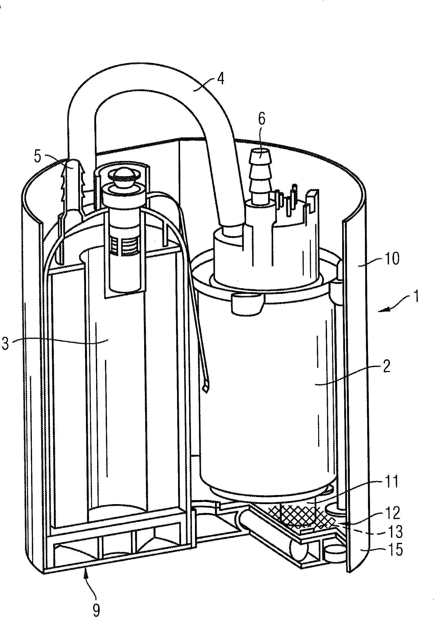
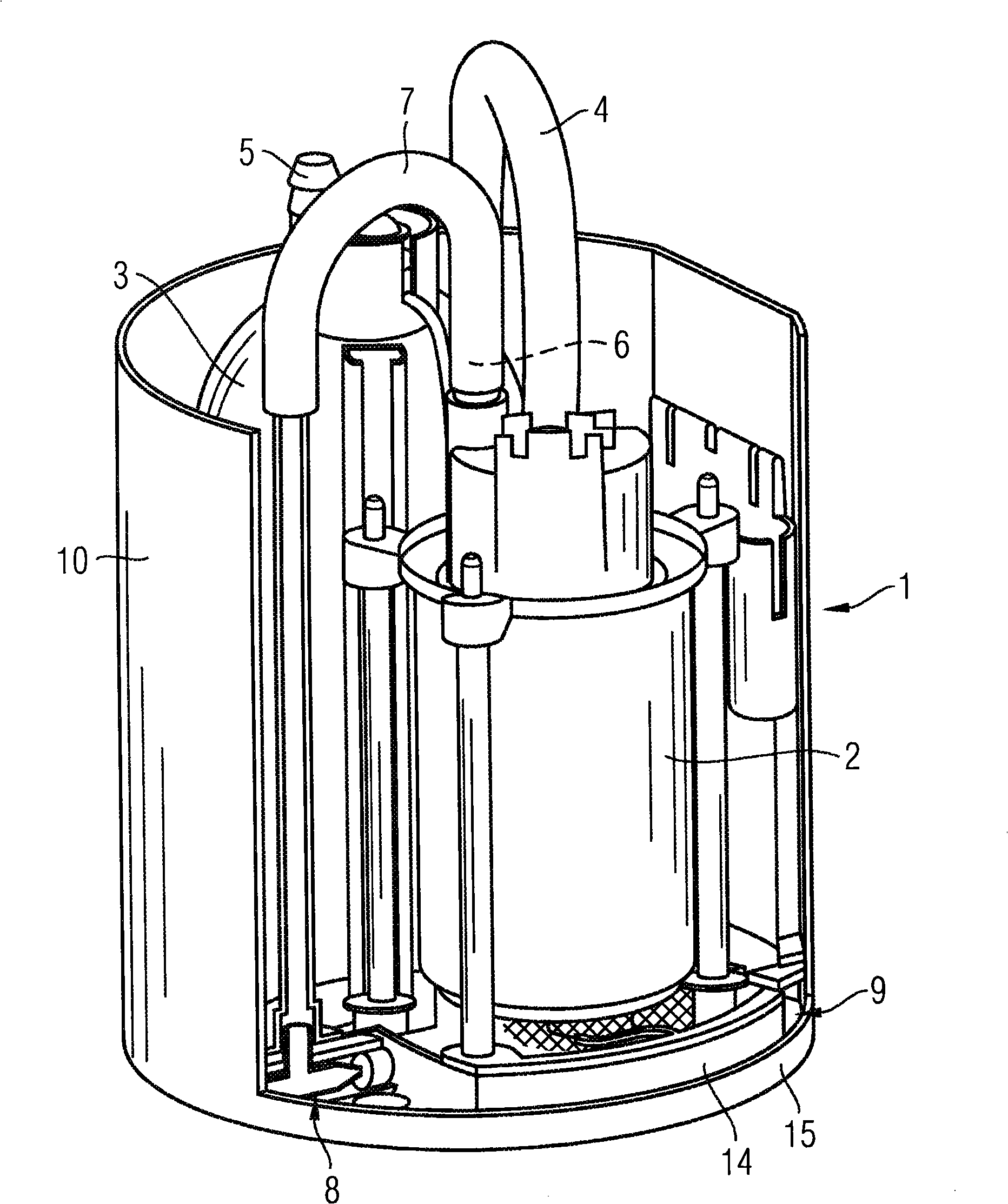
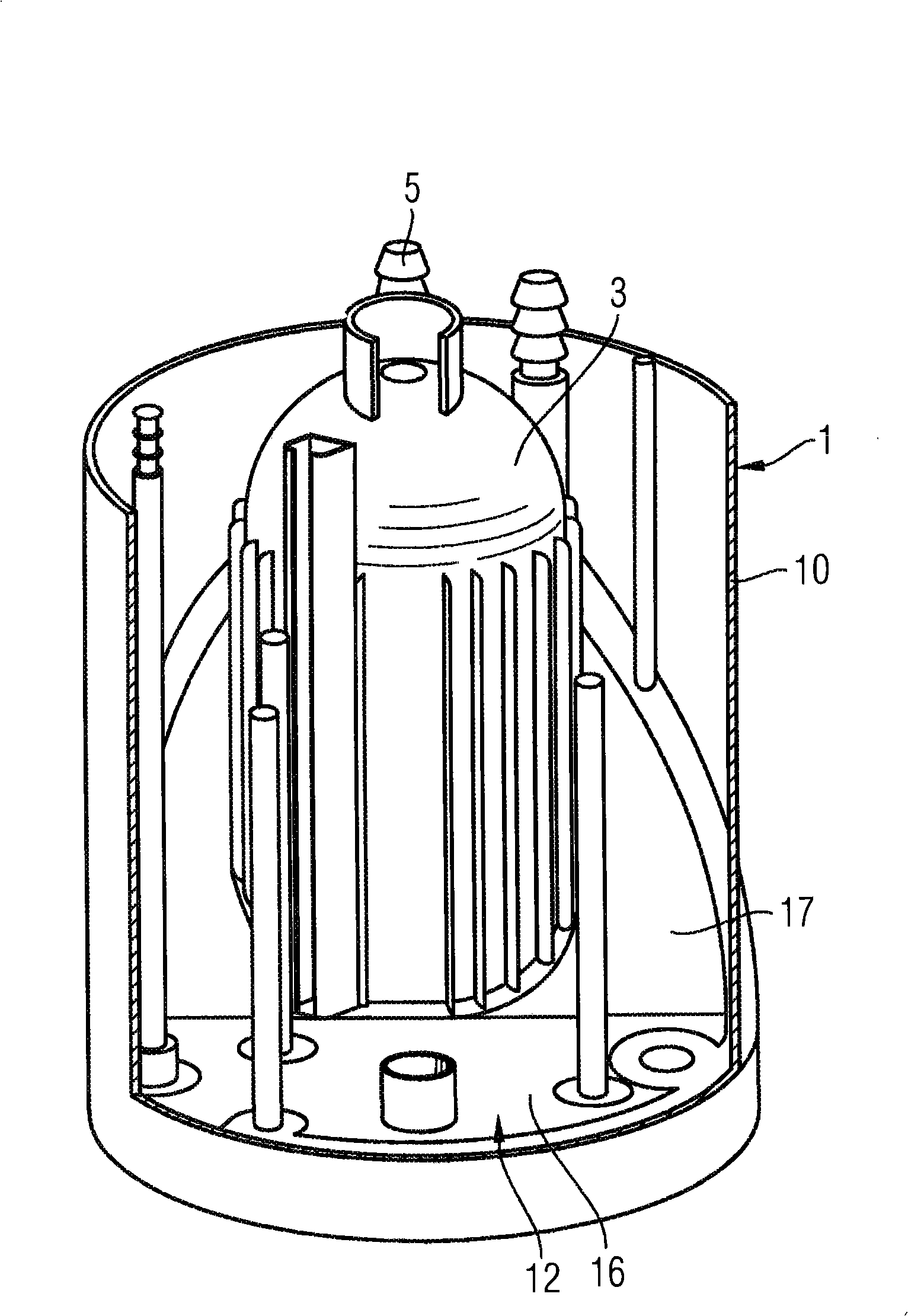
[0020] figure 1 A device is shown for collecting fuel in the fuel tank of the motor vehicle and for feeding the collected fuel to a not shown internal combustion engine of the motor vehicle. The device has an electrically driven fuel pump 2 and a fine filter 3 arranged in a swirl pot 1 . The fine filter 3 is also arranged in the swirl pot 1 and is connected to the fuel pump 2 via a fuel line 4 . Furthermore, the fine filter 3 has a connecting piece 5 for a drain line of the internal combustion engine, not shown, which leads to the fuel tank. exist figure 2 The pipe 7 for the suction injection pump 8 shown in is connected to the connection 6 of the fuel pump 2 . The suction jet pump 8 sucks fuel from around the swirl pot 1 and delivers the fuel to the swirl pot 1 . The swirl pot 1 is used to collect fuel and has a bottom plate 9 and a housing 10 sealingly connected to the bottom plate 9 . The suction connection 11 of the fuel pump 2 protrudes through the prefilter 12 into...


PUM


Abstract

A device for collecting fuel in a fuel tank of a motor vehicle having a prefilter arranged inside a swirl pot. The prefilter has a section rising from a horizontal plane and a section lying in the horizontal plane. The sections of the prefilter are produced as one piece and are connected to the swirl pot. The prefilter has an especially large surface.

Description

technical field [0001] The invention relates to a device for collecting fuel in a fuel tank of a motor vehicle, the device having: a swirl tank; a suction connection for a fuel pump; a prefilter covering the suction connection. Background technique [0002] Such devices are frequently used in today's fuel tanks and are known from practice. The prefilter is often designed as a flat part in the base state and rests against the contour of the device in the installed position. The fuel pump arranged in the anti-swirl tank draws fuel through the pre-filter. [0003] A disadvantage of the known device is that the prefilter is a complex component to install. Furthermore, the available filter area of ​​the prefilter is limited due to the close proximity to the components of the device. Contents of the invention [0004] The object of the invention is to improve a device of the type mentioned at the outset so that it can be installed particularly easily and the prefilter has a l...

Claims


Application Information

Patent Timeline
Patent Type & Authority Patents(China)
IPC IPC(8): B60K15/077F02M37/10F02M37/44F02M37/50
CPCB60K2015/03111F02M37/106F02M37/22Y10T137/86043Y10T137/86035Y10T137/7976F02M37/44F02M37/50B60K15/077F02M37/10B60K15/03
Inventor 卡尔·埃克迪特尔·哈吉斯特马蒂亚斯·卡德莱尔马丁·马斯奥利弗·舍纳特米夏埃尔·泰歇特
Owner CONTINENTAL AUTOMOTIVE GMBH
Learn More