A metal fitting for power lines

A technology for power lines and fittings, applied in the field of fittings, can solve problems such as time-consuming and labor-intensive, and achieve the effects of easy use, firm locking, and simple structure

Active Publication Date: 2022-05-06
SUIZHOU POWER SUPPLY COMPANY STATE GRID HUBEI ELECTRIC POWER
View PDF4 Cites 0 Cited by
  • Summary
  • Abstract
  • Description
  • Claims
  • Application Information

AI Technical Summary

Problems solved by technology

[0004] The above prior art has the following shortcomings: 1. The clampable cable is limited by the inner diameter of the semi-circular ring. When the outer diameter of the clamped cable is too small, it is necessary to replace the fitting with a smaller semi-circular ring; 2. The fitting clamp Fasteners such as bolts need to be used for fixing, and hardware, fastening parts and other parts and special tools such as wrenches need to be carried during installation, which is time-consuming and laborious

Method used


Image

  • A metal fitting for power lines
  • A metal fitting for power lines
  • A metal fitting for power lines

Examples


Embodiment 1

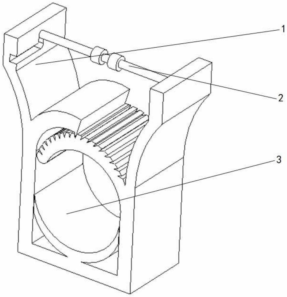
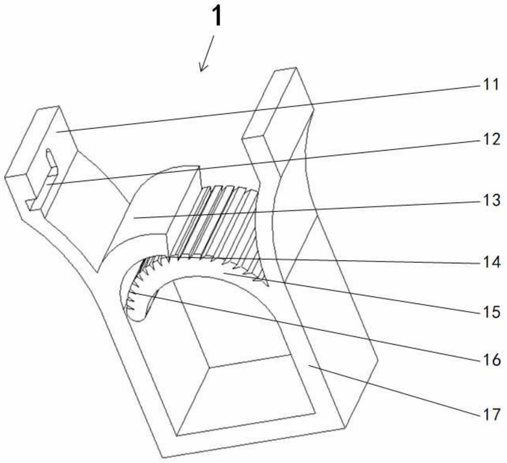
[0033] please see Figure 1 to Figure 4 , a metal fitting for a power line, having a fitting main body 1, characterized in that the fitting main body 1 is composed of a U-shaped wall body 17 and extrusion parts 11 located at both ends of the U-shaped wall body 17, and the U-shaped wall body 17 has two The end is bent to the outside, and the inner wall on the left side of the U-shaped wall body 17 is provided with a first buckle body 13 inwardly, and a locking tooth 14 is arranged below the end of the first buckle body 13, and the inner side of the right side of the U-shaped wall body 17 The wall is provided with an upwardly curved arc-shaped second buckle main body 15 inwardly, and a plurality of buckle grooves 16 are formed along the upper surface of the second buckle main body 15, and the first buckle main body 13 presses the second buckle main body 15 against the Below, the locking tooth 14 is locked in the locking groove 16, the tooth tip of the locking tooth 14 and the lo...

Embodiment 2

[0035]A kind of fittings for power lines, which has a fittings main body 1, characterized in that the fittings main body 1 is composed of a U-shaped wall body 17, extrusion parts 11 located at both ends of the U-shaped wall body 17, and the two ends of the U-shaped wall body 17 Bending outwards, the inner side wall on the left side of the U-shaped wall body 17 is provided with a first buckle body 13 inwardly, and a locking tooth 14 is arranged below the end of the first buckle body 13, and the inner side wall on the right side of the U-shaped wall body 17 An upwardly curved arc-shaped second buckle body 15 is provided inwardly, and a plurality of buckle grooves 16 are formed along the upper surface of the second buckle body 15, and the first buckle body 13 presses the second buckle body 15 below , the locking tooth 14 is stuck in the slot 16, the tip of the locking tooth 14 and the slot 16 and the tip of the slot face to the left, the first buckle main body 13 and the second bu...

Embodiment 3

[0038] please see Figure 4 to Figure 7 , a metal fitting for a power line, having a fitting main body 1, characterized in that the fitting main body 1 is composed of a U-shaped wall body 17 and extrusion parts 11 located at both ends of the U-shaped wall body 17, and the U-shaped wall body 17 has two The end is bent to the outside, and the inner wall on the left side of the U-shaped wall body 17 is provided with a first buckle body 13 inwardly, and a locking tooth 14 is arranged below the end of the first buckle body 13, and the inner side of the right side of the U-shaped wall body 17 The wall is provided with an upwardly curved arc-shaped second buckle main body 15 inwardly, and a plurality of buckle grooves 16 are formed along the upper surface of the second buckle main body 15, and the first buckle main body 13 presses the second buckle main body 15 against the Below, the locking tooth 14 is locked in the locking groove 16, the tooth tip of the locking tooth 14 and the lo...


PUM


Abstract

The invention belongs to the field of fittings, and in particular relates to a fitting for power lines, which has a fitting body, and is characterized in that the fitting body is composed of a U-shaped wall body and extrusion parts located at both ends of the U-shaped wall body, and the left side of the U-shaped wall body The inner wall of the side is provided with a first buckle main body inwardly, and a locking tooth is arranged under the end of the first buckle main body, and the inner wall of the right side of the U-shaped wall body is provided with an upwardly curved arc-shaped second locking member inwardly. The main body of the buckle forms a plurality of slots along the upper surface of the second buckle main body, and the teeth are locked in the slots. A limiting slot is formed on the inner side wall of the extrusion part on the left side. A suspension support rod, the left end of the suspension support rod is inserted into the limit groove, and the right end of the suspension support rod is fixed to the right extrusion part through a universal joint. The present invention has the advantages of simple structure, convenient use, low cost, firm locking, and portable Convenience and other beneficial effects.

Description

technical field [0001] The invention belongs to the field of fittings, in particular to a fitting for power lines. Background technique [0002] Fittings are an essential tool for overhead cable laying, and are used to load the weight of cables. A line has multiple fittings to fix it. [0003] In the prior art, such as CN105977892A discloses a power suspension wire clamp, including a power suspension wire clamp, including a left pressure plate, a right pressure plate, the lower half of the left pressure plate and the lower half of the right pressure plate are several There are at least 3 pairs of semi-circular rings on the left and right sides, and the threading holes formed by each pair of semi-circular rings are coaxial, and the upper half of the left pressing plate and the upper half of the right pressing plate are cantilevers that engage with each other; There are at least 3 pairs of semi-circular rings engaged with each other on the left and right pressing plates of th...

Claims


Application Information

Patent Timeline
Patent Type & Authority Patents(China)
IPC IPC(8): H02G7/05
CPCH02G7/05
Inventor 张建强
Owner SUIZHOU POWER SUPPLY COMPANY STATE GRID HUBEI ELECTRIC POWER
Why Eureka
Try Eureka