Fuel delivery unit

A technology of conveying unit and fuel oil, which is used in transportation and packaging, engine components, liquid fuel feeders, etc., can solve the problem of high cost of filter components, and achieve the effect of simple installation and large surface area

Inactive Publication Date: 2009-07-22
CONTINENTAL AUTOMOTIVE GMBH
View PDF0 Cites 0 Cited by
  • Summary
  • Abstract
  • Description
  • Claims
  • Application Information

AI Technical Summary

Problems solved by technology

A disadvantage of this known fuel delivery unit is that the different filter elements available are very expensive

Method used


Image

  • Fuel delivery unit
  • Fuel delivery unit
  • Fuel delivery unit

Examples


Embodiment Construction

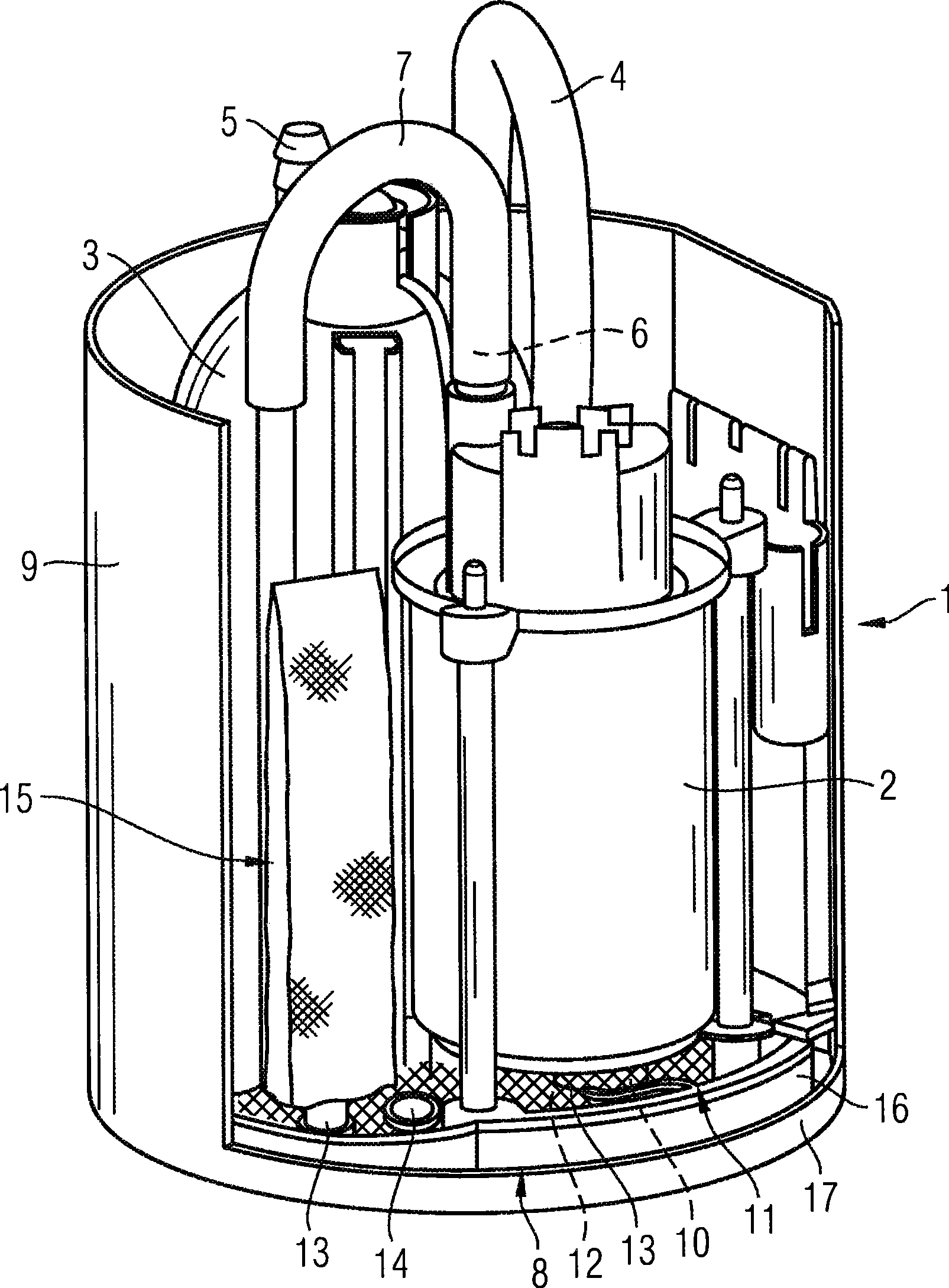
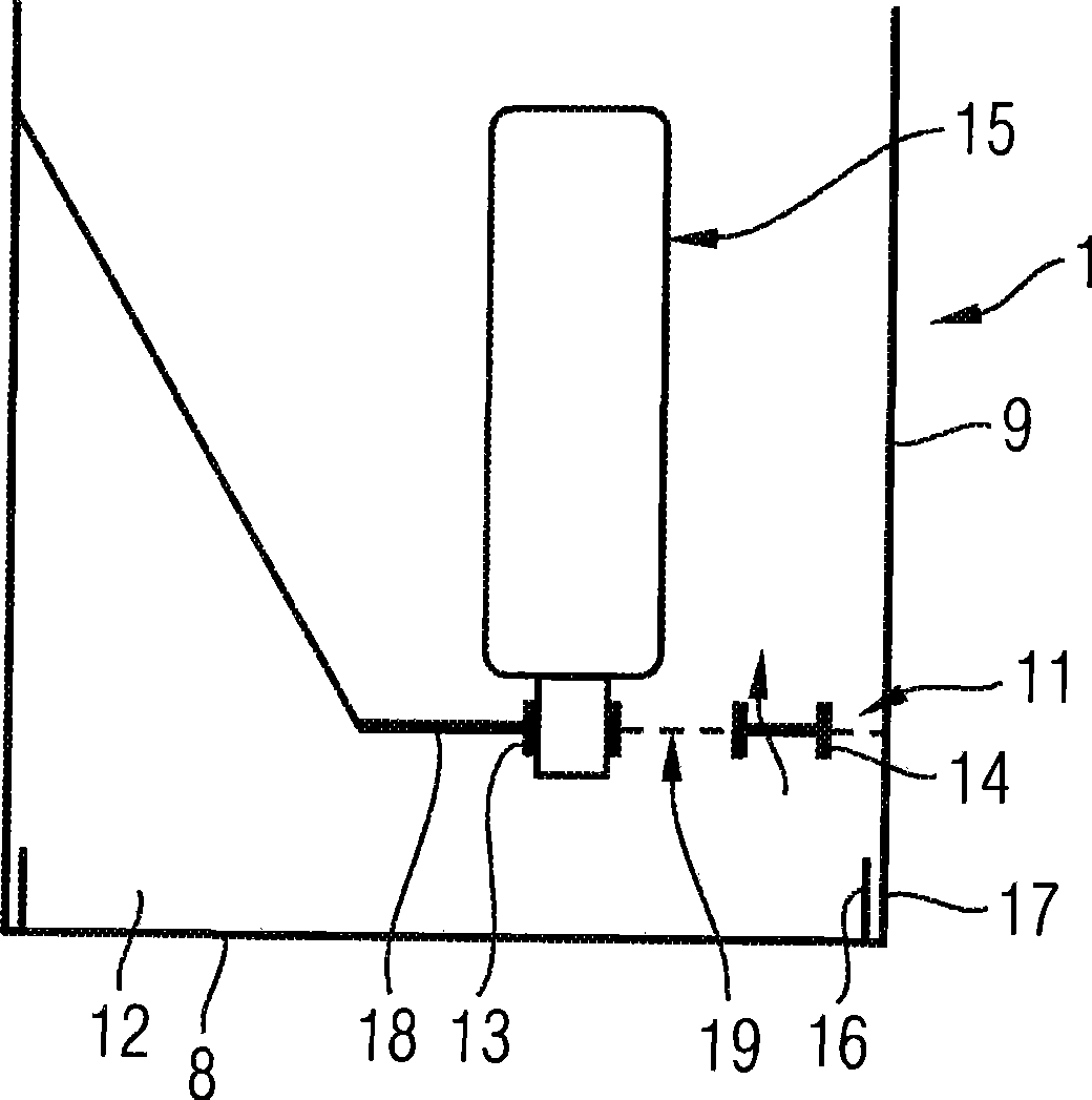
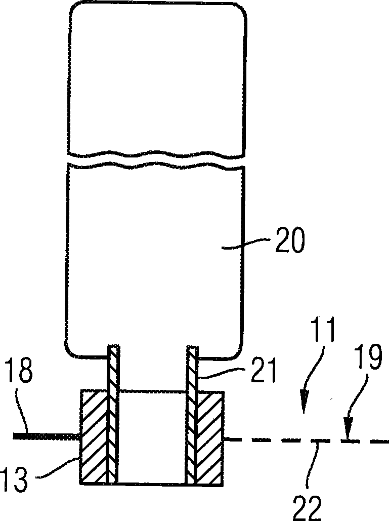
[0018] figure 1 Shown is a feed unit arranged in a fuel tank (not shown) of the motor vehicle, which feed unit is used to feed fuel to an internal combustion engine (also not shown) of the motor vehicle. The delivery unit has an electrically driven fuel pump 2 and a fine filter 3 arranged in a swirl pot 1 . The fine filter 3 is also arranged in the swirl pot 1 and is connected to the fuel pump 2 via a fuel line 4 . Furthermore, the fine filter 3 has a drain connection 5 for the drain of the internal combustion engine leading to the fuel tank. A line 7 for a suction injection pump (not shown) is connected to the connection 6 of the fuel pump 2 . The suction jet pump sucks in fuel from the surrounding environment of the swirl pot 1 and delivers it into the swirl pot 1 . The swirl pot 1 serves to collect fuel and has a bottom plate 8 and a housing 9 connected to the bottom plate 8 in a sealing manner. A suction connection 10 of the fuel pump 2 protrudes through a prefilter 11...


PUM


Abstract

A fuel delivery unit of a motor vehicle comprises a prefilter (11) arranged inside a swirl pot (1), said prefilter having a filter element (19), and at least one connection piece (13, 14) for connecting a supplementary filter element (15). The at least one connection piece (13, 14), in its initial condition, is closed, and is opened when the supplementary filter element (15) is attached. The invention allows the fuel delivery unit to be adapted to projected filter surfaces of the prefilter (11).

Description

technical field [0001] The invention relates to a fuel delivery unit of a motor vehicle, having a swirl pot and a prefilter for filtering the fuel flowing into the swirl pot, the prefilter having a filter element. Background technique [0002] Delivery units with such swirl pots are frequently used in modern motor vehicles and are known from practice. In known delivery units, the swirl pot is connected to the filter element of the prefilter. If a correspondingly large filter efficiency of the prefilter is to be ensured, correspondingly large filter elements of the prefilter are used. A disadvantage of this known fuel delivery unit is that the different filter elements available are very expensive. Contents of the invention [0003] The object of the present invention is to develop a fuel delivery unit of the type mentioned at the outset in such a way that it can be adapted particularly inexpensively to a predetermined filter efficiency. [0004] According to the inventi...

Claims


Application Information

Patent Timeline
Patent Type & Authority Applications(China)
IPC IPC(8): F02M37/10
CPCB60K2015/03105F02M37/106B60K2015/03236B60K2015/03111B60K15/077F02M2037/228F02M37/50Y10T137/4891Y10T137/85978
Inventor 卡尔·埃克迪特尔·哈吉斯特马蒂亚斯·卡德莱尔马丁·马斯奥利弗·舍纳特米夏埃尔·泰歇特
Owner CONTINENTAL AUTOMOTIVE GMBH
Why Eureka
Try Eureka