

Method and apparatus for configuring uplink detection reference signal
A technology of detection reference signal and detection period, which is applied in wireless communication, communication between multiple stations, network planning, etc., and can solve problems such as no configuration scheme proposed.
- Summary
- Abstract
- Description
- Claims
- Application Information
AI Technical Summary
Problems solved by technology
Method used
Image

Examples
Embodiment 1
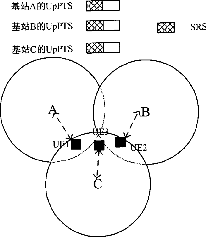
[0025] Embodiment 1: The positions of the SRSs of the neighboring cells in the symbol positions occupied by the UpPTS are configured to be the same.
[0026] The specific implementation process of this embodiment includes the following steps:
[0027] Step A1: Determine the position of the SRS in the UpPTS, and use the same SD-FDMA symbol in the wireless frame UpPTS of all adjacent cells as the starting position of the SRS;
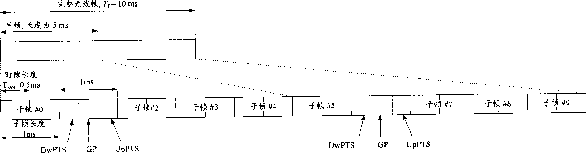
[0028] Step B1: According to the determined position of the SRS, and according to the different requirements of each UE in the cell for the uplink detection cycle and bandwidth, the appropriate time-frequency domain positions for different UEs to send the SRS are scheduled through scheduling signaling, so-called time-domain positions Refers to each symbol position in the UpPTS, and the so-called frequency domain position refers to which frequency resource blocks are on these symbol positions;
[0029] Step C1: Notifying the UE of the time-frequency locat...
Embodiment 2
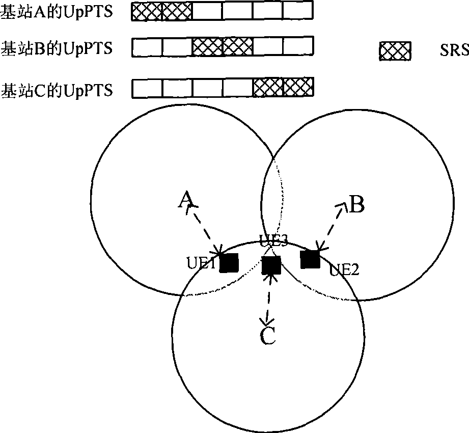
[0033] Embodiment 2: The start and end positions of the symbol positions occupied by the UpPTS of the SRSs of each adjacent cell are configured to be different, so as to achieve the effect of interleaved configuration between cells.
[0034] The specific implementation process of this embodiment includes the following steps:
[0035] Step A2: The SRS configuration device communicates with the base stations of a plurality of neighboring cells, and obtains the UpPTS time slot length (that is, the value of M, which is usually the same for each cell) of each neighboring cell, and the required The number of symbols occupied by the SRS in the UpPTS time slot (that is, the value of N, which may be different for each cell).
[0036] Step B2: The SRS configuration device configures the SRS in the UpPTS by using the method of time division multiplexing (TDM) according to the obtained UpPTS time slot length M of each adjacent cell and the number of symbols N occupied by the SRS, that is,...
Embodiment 3
[0041] Embodiment 3: The configuration position of the SRS in the UpPTS is randomly selected for each adjacent cell, for example, the cell number of each cell may be used as a random seed to select with a certain random algorithm.
[0042]The specific implementation process of this embodiment is similar to the second embodiment, except that the specific method of configuring the SRS position in the step B2 is different. A random selection algorithm is used to make each cell randomly select N symbols for configuration from the available M symbols. Send SRS, this selection can be repeated multiple times with the system running and dynamically or semi-statically updated, and ensure that the probability of M symbols being selected is the same, so that the SRS collision probability of adjacent cells is greatly reduced, effectively reducing the SRS inter-cell interference. For example, if Figure 4 As shown, taking M=2, N=1 as an example, at a certain time T1, base station A select...
PUM
 Abstract
Description
Claims
Application Information