Solar cell panel
A technology of solar cells and solar cell components, applied in solar thermal power generation, solar thermal devices, solar thermal energy, etc., can solve problems such as inability to obtain output
- Summary
- Abstract
- Description
- Claims
- Application Information
AI Technical Summary
Problems solved by technology
Method used
Image

Examples
no. 1 Embodiment approach
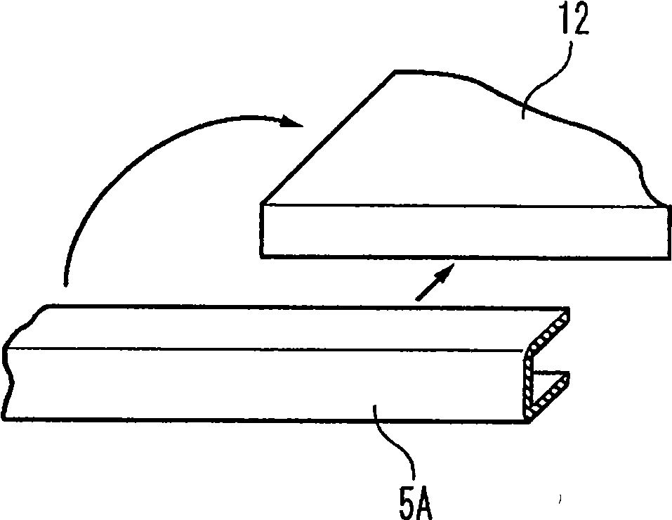
[0063] Figure 3A and Figure 3B It is a perspective view showing an example of a case where a substantially U-shaped spacer 5A is attached around a rectangular flat solar cell module main body 12 . Such as Figure 3A As shown, if a liner 5A is rolled around the whole circumference of the solar cell module body 12, then as Figure 3B As shown, overlapping portions 5A-1 appear at the corners, making it difficult to assemble to the frame structure. and also, Figure 4A and Figure 4B It is a perspective view showing an example of a case where a substantially U-shaped gasket 5B is attached around a rectangular flat solar cell module main body 12 . Such as Figure 4A As shown, if four gaskets 5B are respectively installed on the four sides of the solar cell module body 12, then as Figure 4B As shown, the pads contact each other at the corners only at point 5B-1. Thus, it is not sufficient to prevent water from infiltrating into the solar cell module main body.
[0064] ...
no. 2 Embodiment approach
[0069] Next, a solar cell panel according to a second embodiment of the present invention will be described. Figure 7A and Figure 7B It is a cross-sectional view showing the state before and after fitting the gasket 5C and the solar cell module main body 12 . Figure 7A Indicates the state before chimerism, Figure 7B Indicates the state after fitting. Such as Figure 7A As shown, the section of the liner 5C is roughly U-shaped, such as Figure 7B As shown, when the solar cell module main body 12 and the gasket 5C are fitted, the front end of the gasket 5C is lifted, and water may be allowed to infiltrate into the solar cell module main body 12 .
[0070] Figure 8A and Figure 8B It is a cross-sectional view showing the state before and after fitting of the gasket and the solar cell module body according to the second embodiment of the present invention. In the present invention, as Figure 8AAs shown, protrusions 6-4 are formed at respective ends of the upper side ...
no. 3 Embodiment approach
[0072] Next, a solar cell panel according to a third embodiment of the present invention will be described. Figure 9A and Figure 9B It is a cross-sectional view showing the state that the gasket and the solar cell module body were fitted. Such as Figure 9A As shown, between the spacer 5D and the solar cell module main body 12, a small space is sometimes formed. A small amount of moisture 10 may infiltrate into this space due to capillarity, dew condensation, or the like. Therefore, in the present invention, as Figure 9B As shown, the gasket 6D is provided with holes 6-5, which can discharge these moistures as shown by the arrows in the figure. In this case, the amount of water infiltrated inside is small, and is held in a small gap between the gasket 6D and the solar cell module main body 12 due to surface tension and capillary phenomenon. Therefore, such moisture is removed mainly by evaporation. Therefore, it is preferable that the holes 6-5 of the spacer 6D are la...
PUM
 Abstract
Description
Claims
Application Information
 - R&D
- Intellectual Property
- Life Sciences
- Materials
- Tech Scout
- Unparalleled Data Quality
- Higher Quality Content
- 60% Fewer Hallucinations
Browse by: Latest US Patents, China's latest patents, Technical Efficacy Thesaurus, Application Domain, Technology Topic, Popular Technical Reports.
© 2025 PatSnap. All rights reserved.Legal|Privacy policy|Modern Slavery Act Transparency Statement|Sitemap|About US| Contact US: help@patsnap.com