Individual object conveying device

A technology for conveying devices and objects, which is applied in the direction of conveyor objects, transportation and packaging, and manipulators. It can solve problems such as energy loss and mechanical loss, reduce movement accuracy, and increase noise in the working environment, so as to reduce energy loss and mechanical damage. Loss, avoid swing and jitter, improve the effect of action accuracy

Active Publication Date: 2011-08-24
GUANGZHOU TECH LONG PACKAGING MACHINERY CO LTD
View PDF1 Cites 0 Cited by
  • Summary
  • Abstract
  • Description
  • Claims
  • Application Information

AI Technical Summary

Problems solved by technology

[0003] 1. During the working process, the disc (including the ram and the guide groove) needs to rotate around the pivot (18), and its moment of inertia is large, which will affect the movement accuracy of the gripping head, and the movement is not accurate when picking and gripping the object ;
[0004] 2. The ram protrudes longer, which is 3 to 5 times that of the driving swing arm, and the gap between the guide wheel and the cam groove on the drive swing arm will be enlarged at the front end of the ram. At the same time, after the collision between the guide wheel and the cam groove There will be rebound, which will cause the guide wheel to swing in the cam groove, which will cause the ram part to vibrate, and also reduce the accuracy of the action;
[0005] 3. Similarly, when the disk (including the ram and the guide groove) rotates around the pivot (18), the moment of inertia is large, resulting in more energy loss and mechanical loss;
[0006] 4. During the working process, since the disc (including the ram and the guide groove) needs to rotate reciprocally around the pivot (18), its motion inertia is relatively large, which also increases the noise in the working environment

Method used


Image

  • Individual object conveying device
  • Individual object conveying device
  • Individual object conveying device

Examples


Embodiment 1

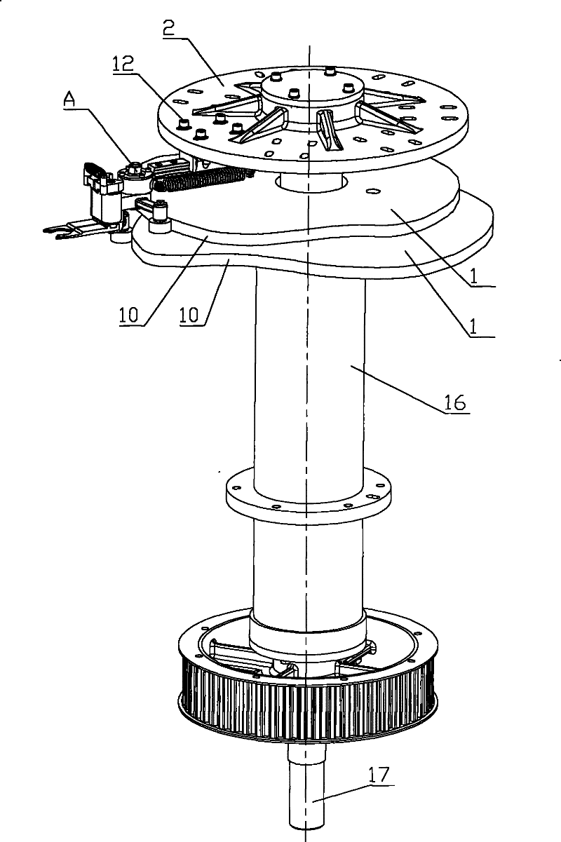
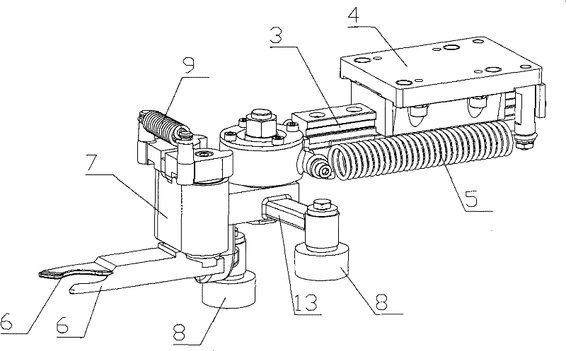
[0033] Such as Figure 1 to Figure 4 As shown, an individual object conveying device includes a cam disc 1, a rotating support 2, a sliding arm 3, a sliding arm seat 4, an elastic reset member, a claw 6, a claw seat 7 and two guide wheels 8, and the rotating support Seat 2 can rotate around its axis (i.e. vertical shaft 17), sliding arm seat 4 is fixed on the rotating support 2, and sliding arm 3 and sliding arm seat 4 slide and cooperate along the longitudinal direction of sliding arm 3, so that sliding arm 3 can rotate along the The bearing 2 reciprocates radially. The front end of the sliding arm 3 is provided with a claw seat rotating shaft 11, and the claw seat 7 is arranged on the front end of the sliding arm 3 through the claw seat rotating shaft 11 and can rotate around the claw seat rotating shaft 11. The gripping claw 6 is arranged on the claw seat 7, and the cam disc 1 is provided with two mutually independent cam curved surfaces 10, two guide wheels 8 are respecti...

Embodiment 2

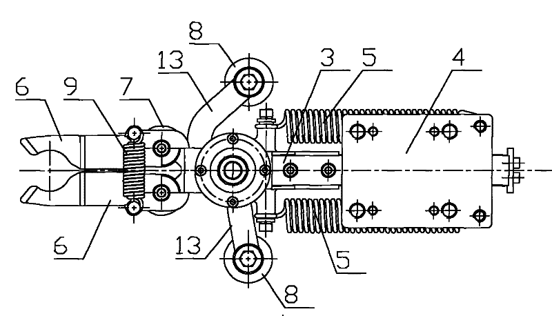
[0044] Such as Figure 5 As shown, the claw seat 7 includes a front seat body 14 and a rear seat body 15, which are connected by a connector (screw 18) between the front seat body 14 and the rear seat body 15, and the claw 6 is arranged on the front seat body 14, and the side arm 13 is provided On the rear seat body 15. Because the claw seat 7 adopts a split structure, during manufacture, the front seat body 14 and the rear seat body 15 can be processed with different materials, such as the rear seat body 15 can be aluminum, light in weight, and the moment of inertia is small, while the front seat body 14 Other materials can be used to ensure its strength.


PUM


Abstract

The invention discloses an individual article transportation device which comprises a circular cam, a rotation support, a slide arm, a slide arm base, an elastic reduction part, a fetch holding claw, a claw base and two guide wheels. The rotation support can rotate around an axis of the rotation support. The slide arm base is fixed on the rotation support. The slide arm and the slide arm base arematched with each other in a sliding way along the vertical direction of the slide arm. And the slide arm can reciprocate along the radial direction of the rotation support. A claw base shaft is arranged on the front end of the slide arm. The claw base is arranged on the front end of the slide arm by the claw base shaft and can rotate around the claw base shaft. The fetch holding claw is arrangedon the claw base. Two sections of mutually independent cam curved surface are arranged on the circular cam. The two guide wheels are respectively arranged on the two sides of the claw base. The elastic reduction part is arranged between the slide arm base and the slide arm or the claw base. Under the effect of the elastic reduction part, the two guide wheels are respectively matched with the two sections of the cam curved surface closely. When the individual article transportation device works, the rotation inertia of the claw base part is small, and the slide arm cannot jitter, so that the action of grasping articles is more accurate. The energy consumption is lowered, and the noises are small.

Description

technical field [0001] The invention relates to an individual item transport device. Background technique [0002] In the beverage or pharmaceutical filling industry, a large number of bottles are used, and during the blowing process of these bottles, individual object conveyors are used, which are used to remove the bottles and transport them to specific positions , and the structure of the existing individual material conveying device is as described in Chinese patent ZL200580007076.6: "The rotating support is driven to rotate continuously around a substantially vertical axis of rotation (A0), and has a conveying arm, the The transfer arm has a disc mounted pivotally relative to said rotating support about a pivot (18) substantially parallel to the axis of rotation (A0) of said support ... said guide groove has a concave groove; the ram is implemented as a single piece generally in the shape of a cam curve, the profile of which is complementary to the profile of the groov...

Claims


Application Information

Patent Timeline
Patent Type & Authority Patents(China)
IPC IPC(8): B25J13/00B65G47/74B65G47/90
Inventor 邹大群宋奎伟林世鸿刘普锋
Owner GUANGZHOU TECH LONG PACKAGING MACHINERY CO LTD
Why Eureka
Try Eureka