

Image splicing method and apparatus
An image stitching and image technology, applied in image data processing, graphic image conversion, instruments, etc., can solve problems such as inability to apply to most users of mobile terminals, large changes in shooting angles, and complex calculation methods.
- Summary
- Abstract
- Description
- Claims
- Application Information
AI Technical Summary
Problems solved by technology
Method used
Image

Examples
Embodiment 1
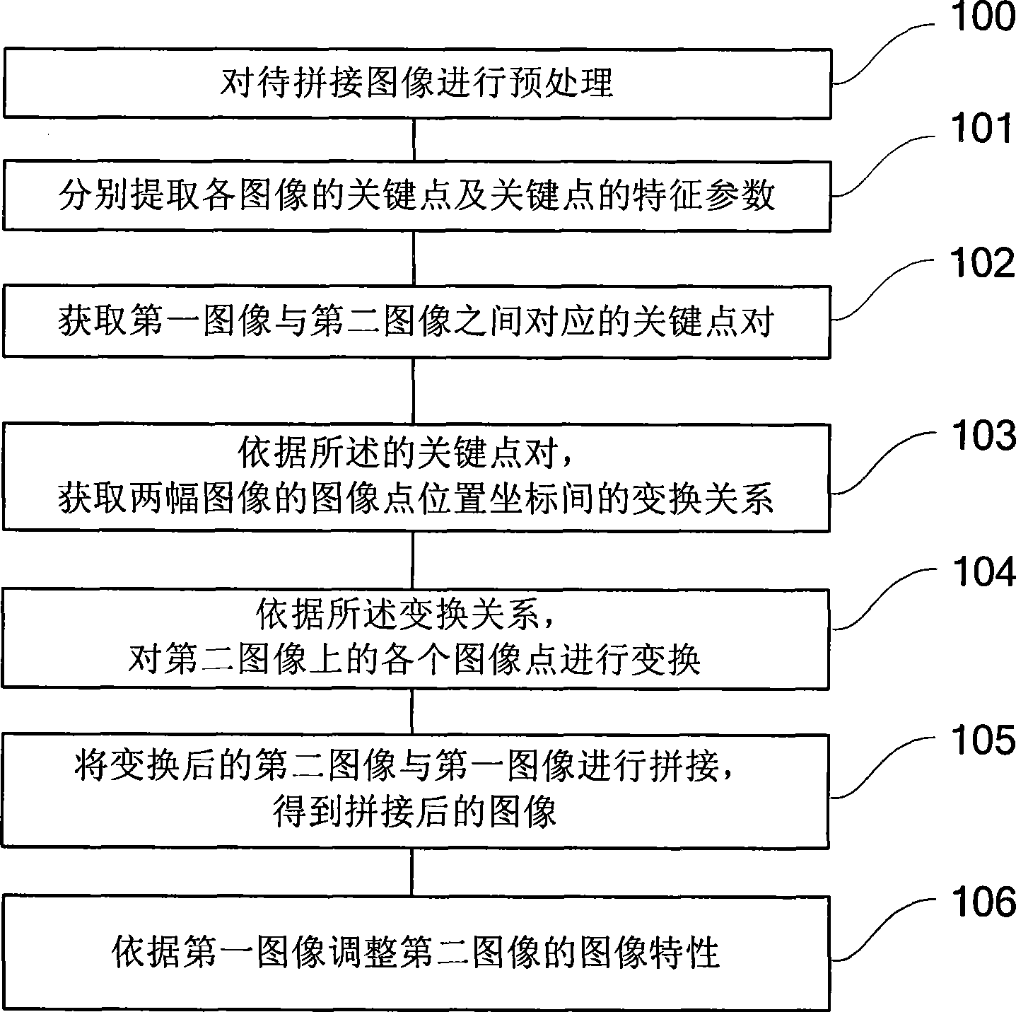
[0057] refer to figure 1 , which shows Embodiment 1 of an image mosaic method according to the present invention, which may specifically include:
[0058] Step 101, for the first image and the second image to be spliced, respectively extract the key points of each image and the characteristic parameters of the key points; the first image and the second image can be selected by the user from the image library;
[0059] Step 102, acquiring keypoint pairs corresponding between the first image and the second image;
[0060] Step 103, according to the key point pair, obtain the transformation relationship between the image point position coordinates of the two images;
[0061] For example, the transformation relationship is obtained by using polynomial fitting regression:
[0062] u = a 0 + a ...
Embodiment approach 1
[0095] The present invention can obtain the corresponding key point pairs between the first image and the second image in the following manner: according to the key points of the first image and their characteristic parameters, a K-d tree is created; for each key point of the second image, the most The adjacent point search algorithm obtains the corresponding key points in the first image to obtain key point pairs.
[0096] The KD-tree technology adopted in the present invention has fast retrieval speed, its space complexity is linearly related to the dimension of the data set, and is compatible with the secondary memory, so it is a very effective index algorithm (which can meet the requirements of mobile The real-time requirements of the terminal). Its basic idea is to divide the dataset into two sub-datasets according to certain criteria, and then recursively split the two sub-datasets to form a retrieval tree.
[0097] The K nearest neighbor (k-Nearest Neighbor, KNN) searc...
Embodiment approach 2
[0099] The present invention also acquires the corresponding key point pairs between the first image and the second image in the following manner:
[0100] (1) Create a K-d tree according to the key points and characteristic parameters of the first image;
[0101] (2) For each key point of the second image, adopt the nearest neighbor point search algorithm to obtain the nearest neighbor key point and the second neighbor key point corresponding to it in the first image;
[0102] (3) Obtain the distance between the key point kp of the second image and the nearest key point kp1 | kp ⇔ kp 1 | , And the distance between the key point kp and the second adjacent key point kp2 | kp ⇔ kp 2 | ;
[0103] (4) Comparing the above two distances, if the preset condition is met, i...
PUM
 Abstract
Description
Claims
Application Information